9
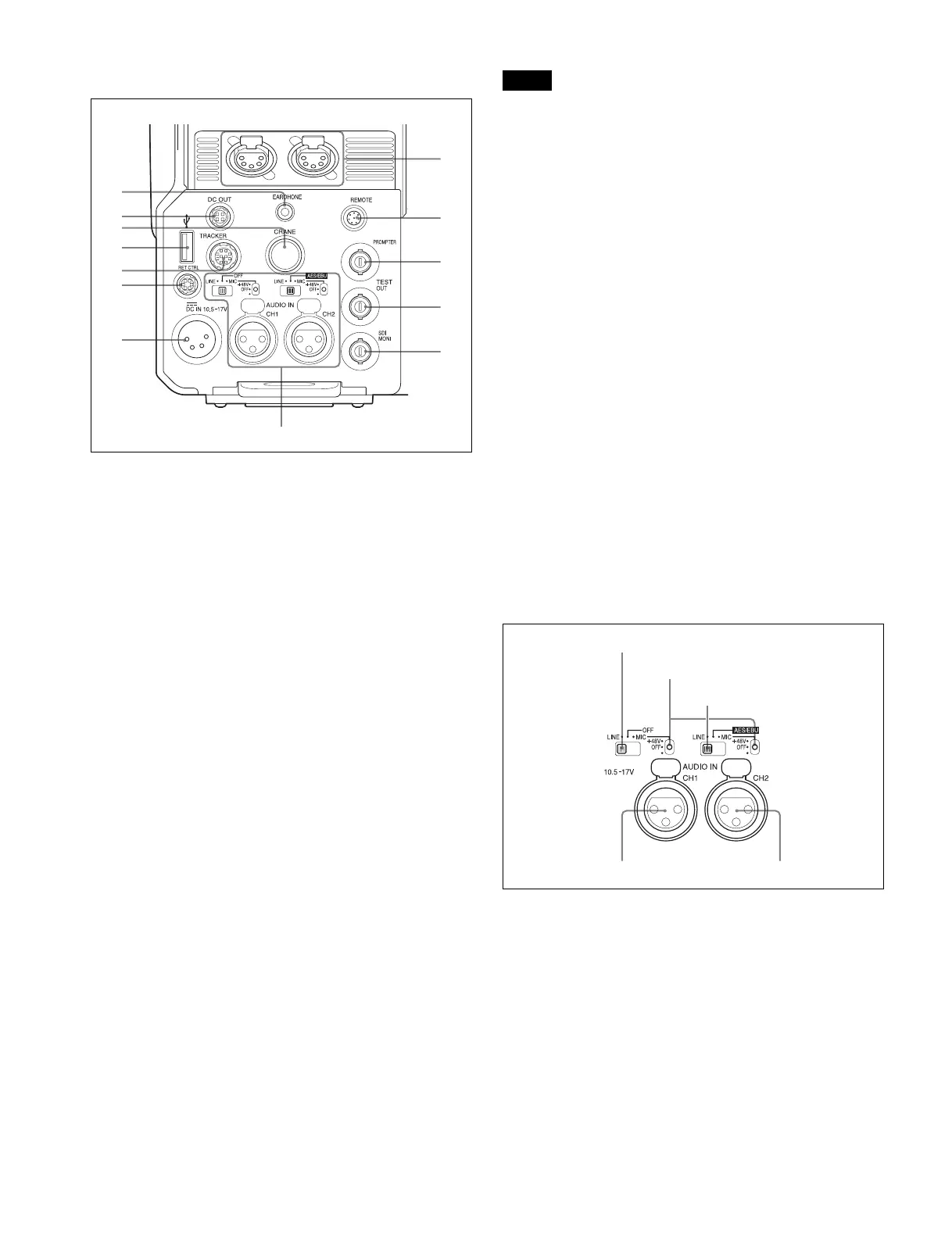
Connector panel
a EARPHONE jack (stereo minijack)
For connecting an earphone or headset to hear the intercom
audio.
The audio level can be adjusted using LEVEL on the
<EARPHONE> page of the OPERATION menu.
b DC OUT (DC power supply output) connector (4-pin)
To supply power to devices such as a wireless receiver
(optional) (max. 0.5 A).
c CRANE connector (12-pin)
For external interface, such as viewfinder and external data.
d USB connector (for connecting a USB drive)
Connect a USB drive to save or load the settings data file.
For details, see “Using a USB Drive” (page 56).
e TRACKER connector (10-pin)
For external interface, such as intercom and tally.
f RET CTRL (return control) connector (6-pin)
For connection to a CAC-6 Return Video Selector.
g DC IN (DC power supply input) connector (XLR 4-pin)
Used for connection to the AC-DN10 AC Adaptor to supply
power to the camera.
h INTERCOM1 and 2 (intercom 1 and 2) connectors (XLR
5-pin)
Used for input and output of intercom audio signals if an XLR
5-pin headset is connected.
The INTERCOM 1 connector can be used for communication
over the engineer line even when the power is off, as long as
the power LED is lit in red.
i REMOTE connector (8-pin)
For connection to an RCP-1000/1500 series Remote Control
Panel, or MSU-1000/1500 Master Setup Unit.
When the camera is connected to a camera control unit, do not
connect any remote control device, such as RCP and MSU, to
this connector.
j PROMPTER (prompter signal output) connector (BNC-
type)
For output of the prompter 1 signal (valid only when a camera
control unit is connected). When a camera control unit having
two prompter inputs is connected, the signal of input 1 is
output from this connector.
k TEST OUT connector (BNC-type)
To output the analog signal.
This also supplies the VBS signal, an HD-Y signal nearly equal
to the signal output from the VF connector, an HD-SYNC
signal, or an SD-SYNC signal depending on which of these
you have selected on the menu.
For details about signal settings, see “Setting the Camera
Outputs” (page 21).
l SDI-MONI (serial digital interface) connector (BNC-
type)
For HD-SDI or SD-SDI signal output.
For details about signal settings, see “Setting the Camera
Outputs” (page 21).
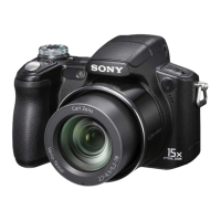
m AUDIO IN CH1 and CH2 connectors (XLR 3-pin) and
switches
Connect audio signals. An input select switch and microphone
power switch are provided for each channel.
CH1 audio input select switch
Set to the appropriate position according to the equipment
connected to the AUDIO IN CH1 connector.
LINE: When a line-level (0 dBu) signal source is connected
MIC: When an external microphone is connected
CH2 audio input select switch
Set to the appropriate position according to the equipment
connected to the AUDIO IN CH2 connector.
LINE: When a line-level (0 dBu) signal source is connected
AES/EBU: When a digital audio signal is connected (the
signal must be in synchronization with the camera
output).
MIC: When an external microphone is connected
b
c
d
e
f
g
h
i
j
k
a
l
m
Note
CH1 audio input select switch
Microphone power switches
CH2 audio input select switch
AUDIO IN CH2 connectorAUDIO IN CH1 connector