– 64 –
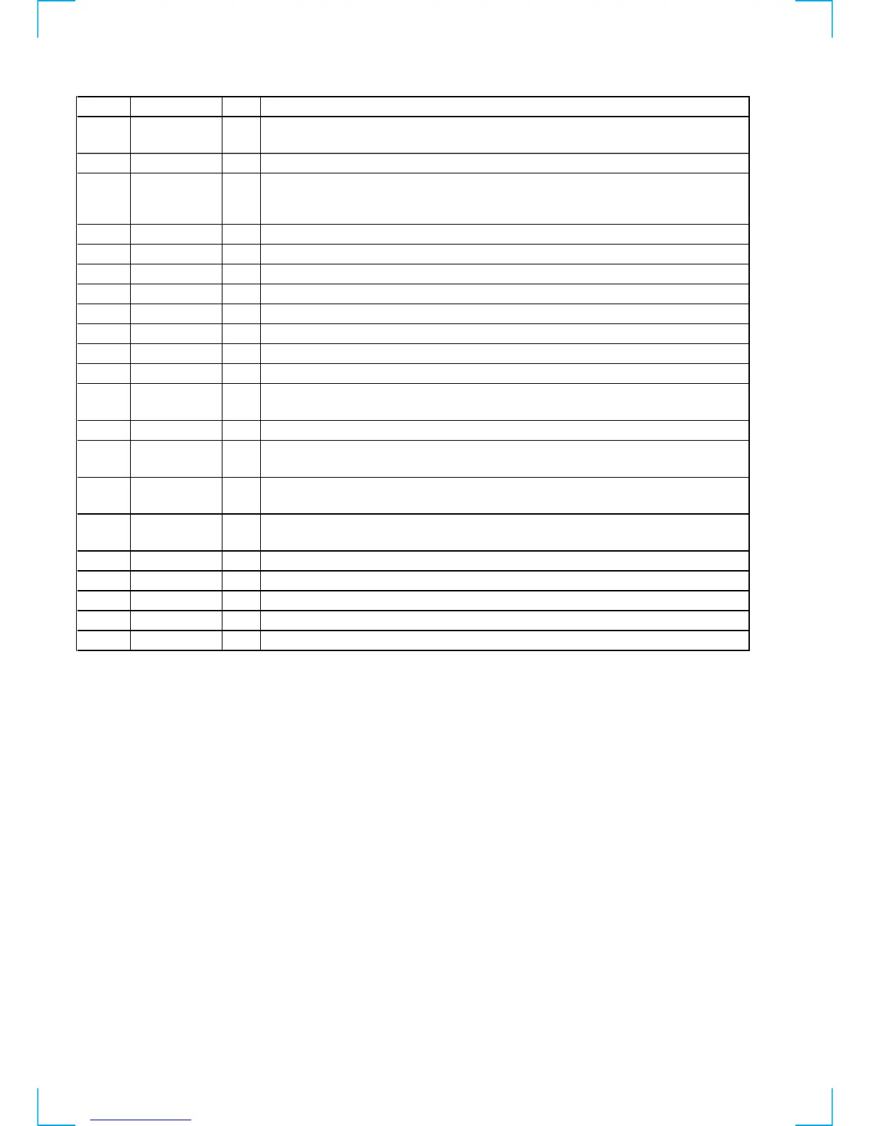
Pin No. Pin Name I/O Description
78
MNT0 (FOK)
I
Focus OK signal input from the CXD2656R (IC121)
“H” is input when focus is on (“L”: NG)
79 SCL O
Clock signal output to the EEPROM (IC171)
80 SCTX O
Recording data output enable signal output to the CXD2656R (IC121) and overwrite head
driver (IC181) Writing data transmission timing output (Also serves as the magnetic head on/off
output)
81 CLOCK SET0
I Destination setting terminal (fixed at “H” in this set)
82 CLOCK SET1
I Destination setting terminal (fixed at “L” in this set)
83
LED0 O LED drive signal output terminal Not used (open)
84 LED1 O
LED drive signal output terminal Not used (open)
85, 86 NC
O Not used (open)
87 MODEL SEL0 I
Setting terminal for the model (fixed at “L” in this set)
88 MODEL SEL1 I
Setting terminal for the model (fixed at “H” in this set)
89, 90 NC
O Not used (open)
91
TIMER I
TIMER switch (S751) input terminal (A/D input)
“L”: PLAY, “H”: REC (OFF: center voltage)
92
SOURCE I INPUT switch (S741) input terminal (A/D input)
93
KEY3 I
Key input terminal (A/D input)
S731 to S733 (PITCH CONTROL, FILTER, TIME keys input)
94
KEY2 I
Key input terminal (A/D input) S721 to S724 (DISPLAY/CHAR, SCROLL, PLAY MODE, I/u
keys input)
95
KEY1 I
Key input terminal (A/D input)
S711 to S714 and S716 (MENU/NO, YES, PUSH ENTER, CLEAR, EJECT § keys input)
96 AVSS
— Ground terminal
97
KEY0 I Key input terminal (A/D input) S701 to S706 (REC r , p, ), 0, P, · keys input)
98 VREF I Reference voltage (+3.3V) input terminal (for A/D converter)
99 +3.3V
— Power supply terminal (+3.3V) (for analog system )
100
MONO/ST
I
REC MODE switch (S746) input terminal “L”: MONO, “H”: STEREO
 Loading...