44
RV500
TP500
(BU+5V)
TP
(GND)
IC800
IC801
IC802
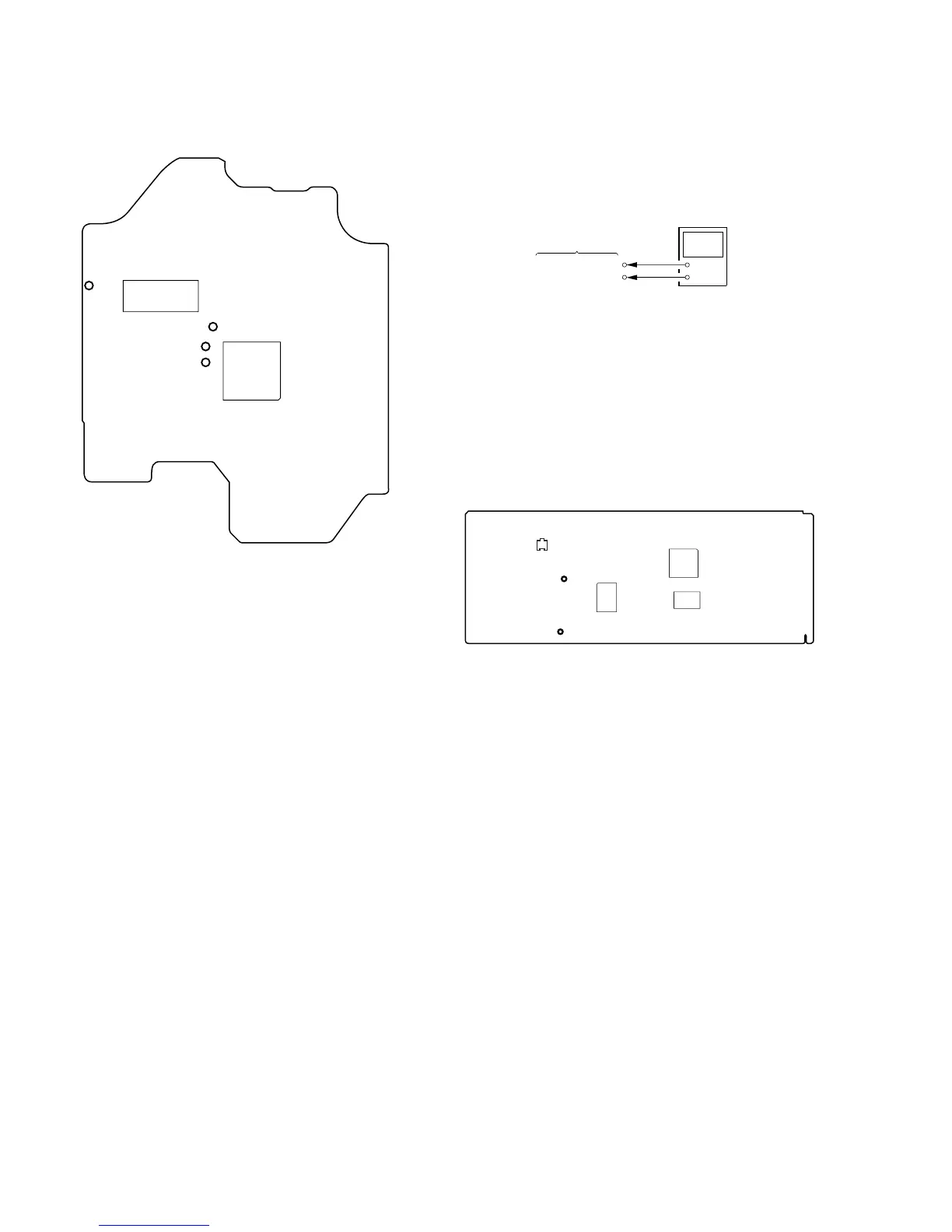
Checking Location:
IC171
IC101
TP
(VC)
TP
(FE)
TP (TE)
TP (RF)
– BD (CD) BOARD (Conductor Side) –
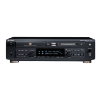
Voltage Adjustment
When replacing the base unit (BU-21BD53), mounted MAIN board
and IC506, R550, R551, or RV500 on the MAIN board, perform
the adjustment with the following procedure.
Connection:
Adjustment procedure:
1. Connect the digital voltmeter to TP500 (BU+5V) and TP
(GND) on the MAIN board.
2. Adjust the RV500 so that the reading of the digital voltmeter
becomes 5.22 ± 0.04 V.
Specified Value:
Digital voltmeter reading: 5.22 ± 0.04 V
Adjustment Location:
+
–
MAIN board
digital voltmeter
TP500 (BU+5V)
TP (GND)
– MAIN BOARD (Component Side) –