Do you have a question about the Sony MXD-D4 and is the answer not in the manual?
Details technical specs for the CD playback section.
Details technical specs for the MD recording/playback section.
Covers power needs, dimensions, mass, and accessories.
Explains how to read and interpret diagnostic displays.
Step-by-step guide to check past errors.
Instructions on how to navigate and select specific error history modes.
Details the process for checking AC leakage on exposed metal parts.
Consolidates various cautions regarding laser, components, and handling.
Guidelines for safely handling the optical pick-up assembly.
Proper method for cleaning the optical pick-up lens.
Safety and procedure for checking laser diode emission.
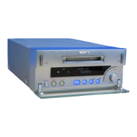
Information on identifying different model versions.
Describes the use of a special jig for waveform analysis on the MD board.
Steps for recording and reading IOP values for optical pick-up replacement.
Procedures for checking key parameters before MD repairs.
Step-by-step instructions to access the service mode.
Lists and describes the various available test modes.
Details procedures for checking software versions and display functionalities.
Covers key/jog input testing and software reset procedures.
Explains how to read and interpret retry cause information in MD operation.
Guide on using a CD-TEXT test disc for display verification.
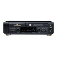
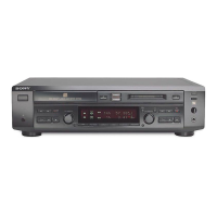
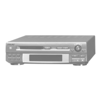
Identifies controls and connectors on the front and rear panels.
Specific instructions for setting the voltage selector on Singapore models.
Outlines the sequence of disassembly steps for the unit.
Details the removal of the outer case and loading panel.
Covers disassembling the front panel and MD mechanism.
Steps for removing the MD board and its associated holder.
Details removal of sliders, levers, and the optical pick-up.
Covers disassembling spindle, sled, loading motors, and the CD mechanism.
Details removing the CD holder and base unit.
Explains the disassembly of the tray, loading board, and cam.
Step-by-step guide for removing the main board.
Essential safety and operational guidelines for entering and using test modes.
Lists available test modes, their numbers, and group assignments.
Explains how to operate continuous playback and recording test modes.
Explains how to interpret mode, error rate, and address displays.
Details the auto-diagnosis function and software version display.
Procedure for addressing "MEMORY NG" errors.
Describes test modes for command transfer and C1/C2 error displays.
Covers various other CD test modes like speed selection and port settings.
Provides a flowchart for checking MD components before replacement.
Presents the general adjustment sequence and initial value settings.
Safety guidelines for checking laser diode emission.
Safe handling and adjustment procedures for the optical pick-up.
Instructions for preparing and using a test disc for bias and error rate checks.
Details essential checks for temperature compensation, laser power, and Iop.
Explains the auto check function and traverse waveform checks.
Covers focus bias checks, error rate analysis, and recording/playback verification.
Details initial adjustment value setting and IOP data recording.
Steps for performing temperature compensation and laser power adjustments.
Procedures for saving IOP data and adjusting traverse function.
Step-by-step guide for adjusting the focus bias.
Procedures for checking error rates on CD and MO discs.
Instructions for performing auto gain control adjustments for CD and MO.
Diagrams showing component placement on the BD (MD) board.
Details how to perform and interpret waveform checks for CD playback.
Steps to perform voltage adjustment on the main board.
Visual representation of the MD servo system's signal flow.
Diagram showing the main board's circuitry and signal paths.
Illustrates the display and power supply circuitry.
Guidance for interpreting PWB layouts and schematic diagrams.
Shows the physical placement of various circuit boards in the unit.
Internal block diagrams for key ICs on the BD (MD) board.
Component layout diagram for the BD (CD) board.
Circuit schematic for the BD (CD) board.
The first section of the BD (MD) board schematic.
The second section of the BD (MD) board schematic.
Component layout diagram for the BD (MD) board.
Displays typical waveforms observed on different circuit boards.
Component placement diagram for the main board's component side.
Component placement diagrams for the main board's conductor side and loading board.
The first section of the main board circuit schematic.
The second part of the main board schematic and the loading board schematic.
The third section of the main board circuit schematic.
The final section of the main board circuit schematic.
Component layout diagrams for display and switch boards.
Circuit schematics for display and switch boards.
Shows component placement for the TRANS board in non-Singapore models.
Provides the circuit schematic for the TRANS board in non-Singapore models.
Illustrates component placement for TRANS/LF boards in Singapore models.
Provides circuit schematics for TRANS/LF boards in Singapore models.
Shows component layout and circuit schematic for the HP board.
Internal block diagrams for key power supply related ICs.
Describes the function of each pin for IC101 on the BD (MD) board.
Describes the function of each pin for IC151 on the BD (MD) board.
Describes the function of each pin for IC800 on the Main board.
Describes the function of each pin for IC801 on the Main board.
Illustrates the disassembled components of the unit's case.
Shows the disassembled parts of the front panel assembly.
Details the disassembled components of the unit's chassis.
Illustrates the first part of the MD mechanism disassembly.
Shows the second part of the MD mechanism disassembly.
Details the disassembled components of the CD mechanism deck.
Lists all electrical components for the BD (MD) board.
Continues the list of electrical components for the BD (MD) board.
Lists all electrical components for the display board.
Lists components for LP LED, HP, LF, and TRANS boards.
Lists all electrical components for the main board.
Continues the list of electrical components for the main board.
Continues the list of electrical components for the main board.
Lists electrical components for the PW SW board.
Lists various screws and hardware used in the unit.
Lists included accessories and packing materials.
| Brand | Sony |
|---|---|
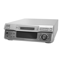
| Model | MXD-D4 |
| Category | MiniDisc Player |
| Language | English |