12
1-686-492-
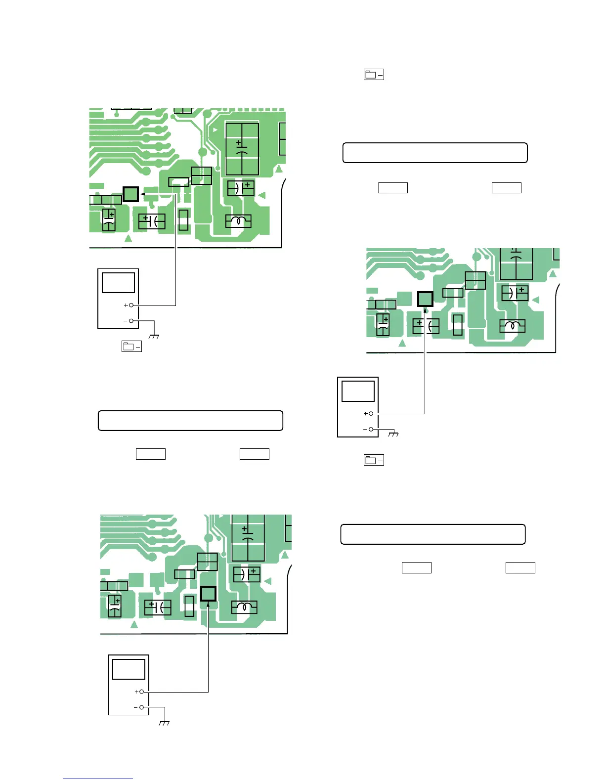
TP908
(REG 1)
TP908
(REG1)
digital voltmeter
5. Press key to write the adjustment value, item No.will
change to 742.
5-4-3. VC1 adjustment method
1. Set the overall adjustment mode and set the item No. to 742.
LCD display
742 Vc1 XX
2. Connect a digital voltmeter to TP902 (VC1) on the main board
and adjust
VOL +
key (Voltage up) and
VOL –
key
(Voltage down) on the remote control.
Adjustment value:2.15V
Standard value:2.14 to 2.155V
MAIN BOARD (SIDE A)
C908C922
C926
L904
C910
C916
R908
R921
R911
2
1-686-492-
TP902
(VC1)
TP902(VC1)
digital voltmeter
3. Press key to write the adjustment value, item No. will
change to 743.
5-4-4. VC2 adjustment method
1. Set the overall adjustment mode and set the item No. to 743.
LCD display
743 Vc2 XX
2. Connect a digital voltmeter to TP907(VC2) on the main board
and adjust
VOL +
key (Voltage down) and
VOL –
key
(Voltage up) on the remote control.
Adjustment value:1.15V
Standard value:1.15 to 1.18V
MAIN BOARD (SIDE A)
C908C922
C926
L904
C910
C916
R908
R921
R91112
1-686-492-
TP907
(VC2)
TP907(VC2)
digital voltmeter
3. Press key to write the adjustment value, item No. will
change to 744.
5-4-5. Class-D power supply adjustment method
1. Set the overall adjustment mode and set the item No. to 744.
LCD display
744 Cls D XX
2. Connect a digital voltmeter to TP909 (Class-D) on the main
board and adjust
VOL +
key (Voltage up) and
VOL –
key
(Voltage down) on the remote control.