Location and Function of Parts and Controls
11
7) Available only when the interlace signal is input. 8) Available only when the resolution of the input signal is
1920 × 1080 or 2048 × 1080.
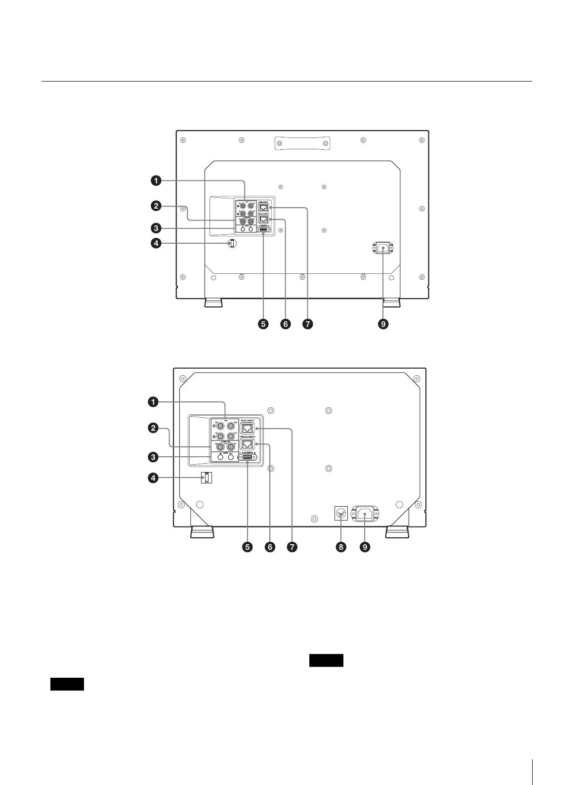
Rear Panel
SDI (3G/HD/SD) input and output connectors
(BNC)
IN connector, IN connector
Input connector for serial digital component signals.
SDI 1 and SDI 2 inputs are available.
OUT connector, OUT connector
Output connector for serial digital component signals.
SDI 1 and SDI 2 outputs are available.
Output is only activated when the power is on.
COMPOSITE input and output connectors
(BNC)
IN connector
Input connector for composite video signals.
OUT connector
Loop-through output connector.
When inputting a video signal with the jitters, etc. the
picture may be disturbed. We recommend using the
TBC (time base corrector).