Do you have a question about the Sony PVM-A250 and is the answer not in the manual?
Detailed procedures for disassembling various components including rear cover, fans, boards, bezel, speaker, and OLED module.
Troubleshoots the issue of the front panel power LED blinking red, requiring PC connection and setup.
Describes LED indicators on the QBC board and the corresponding failure conditions and remedies.
Explains G2 board LED status, normal operation states, power failure diagnosis, and AC voltage diagnostics.
Flowchart for diagnosing why the system does not start, checking harnesses and board replacements.
Troubleshooting steps for abnormalities in control operation, checking harnesses and remote operation.
Provides important notes regarding repair parts, including safety warnings, standardization, stock availability, and harnesses.
| 3D | No |
|---|---|
| Screen shape | Flat |
| Response time | - ms |
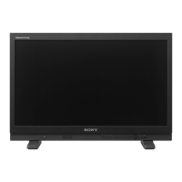
| Display diagonal | 24.5 \ |
| Display technology | - |
| Native aspect ratio | 16:9 |
| Viewable size, vertical | 305.6 mm |
| Viewable size, horizontal | 543.4 mm |
| Display brightness (typical) | - cd/m² |
| RMS rated power | 1 W |
| Number of speakers | 1 |
| Ethernet LAN data rates | 10, 100 Mbit/s |
| Product color | Black |
| Ethernet interface type | Fast Ethernet |
| SDI inputs | 3 |
| RJ-45 ports quantity | 2 |
| Headphone connectivity | 3.5 mm |
| VGA (D-Sub) ports quantity | 0 |
| AC input voltage | 100 - 240 V |
| AC input frequency | 50 - 60 Hz |
| Power consumption (max) | 115 W |
| Power consumption (standby) | - W |
| Power consumption (typical) | 80 W |
| Storage temperature (T-T) | -20 - 60 °C |
| Operating temperature (T-T) | 0 - 35 °C |
| Storage relative humidity (H-H) | 0 - 90 % |
| Operating relative humidity (H-H) | 30 - 85 % |
| Depth (without stand) | 65.5 mm |
|---|---|
| Width (without stand) | 581 mm |
| Height (without stand) | 386.6 mm |
| Weight (without stand) | 6100 g |