2-1 (E)
PVM-A250
Section 2
Circuit Description
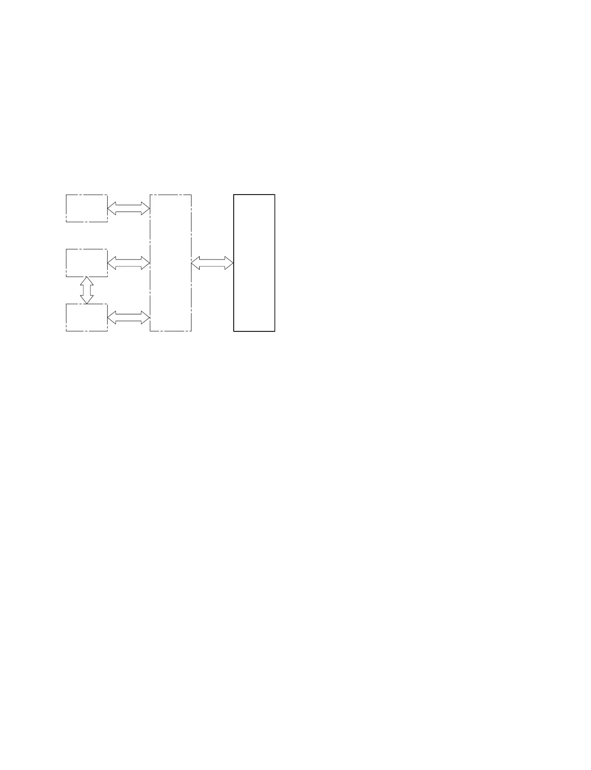
G2
H1
H2
QBC
OLED
MODULE
2-1. Board Configuration
The whole block and board configuration of this unit are as follows:
. G2 board: Power board
. H1 board: User control interface board
. H2 board: Headphone/USB terminal-mounted board
. QBC board: Video/audio/communication input/output and OLED module control board
2-2. G2 Board
The G2 board is used for AC and inputs. It generates the power used in this unit.
During AC input, the G2 board generates 28 V through a power-factor improvement regulator using an
insulating converter and outputs it to a QBC board. The G2 board also generates 12.5 V in two channels
from 28 V using a step-down DC/DC converter and outputs it to the QBC board.
2-3. H1 Board
The H1 board mounts a power switch, input selector button, function button, and rotary encoder.
2-4. H2 Board
The H2 board mounts a headphone terminal and USB terminal (for function extension in future).