2-10
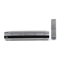
1 SCREW
2 BRAKET GEAR
4 GEAR JOINT 1
3 GEAR JOINT 2
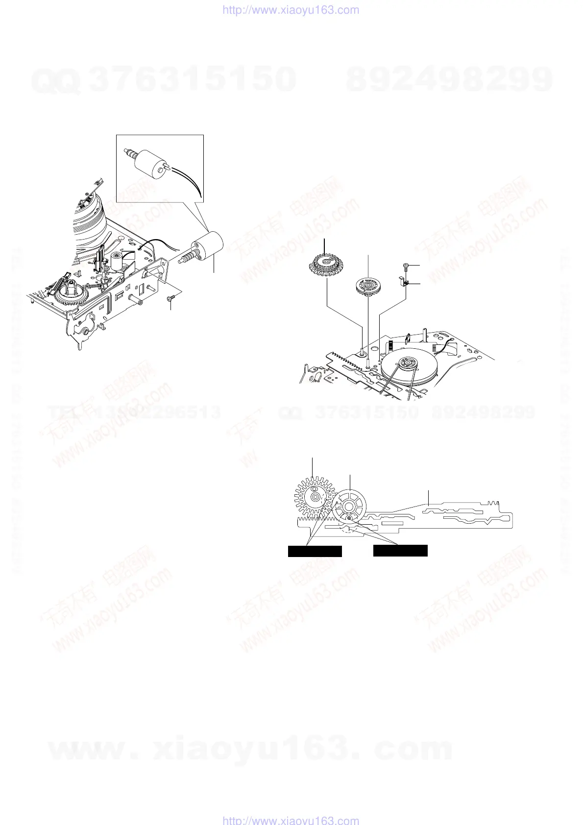
2 MOTOR LOADING ASS`Y
1 SCREW
2-4-7 Motor Loading Ass’y Removal
1) Remove the screw 1.
2) Remove the Motor Loading Ass’y 2.
Fig.2-18 Motor Loading Ass’y Removal
2-4-8 Bracket Gear, Gear Joint 2, 1 Removal
1) Remove the SCREW 1.
2) Remove the Bracket Gear 2.
3) Remove the Gear Joint 2 3.
4) Remove the Gear Joint 1 4.
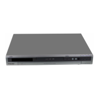
Assembly:
1) Be sure to align dot mark of Gear Joint 1 1 with dot mark of
Gear Joint 2 2 as shown Fig 2-20.
(Refer to Timing point1)
2) Confirm the Timing Point 2 of the Gear Joint 2 2 and Slider
Cam 3.
Fig. 2-19 Bracket Gear, Gear Joint 1,2 Removal
Fig. 2-20 Gear Joint 1,2 Assembly
1 GEAR JOINT1
2 GEAR JOINT2
3 SLIDER CAM
TIMING POINT 1
TIMING POINT 2
w
w
w
.
x
i
a
o
y
u
1
6
3
.
c
o
m
Q
Q
3
7
6
3
1
5
1
5
0
9
9
2
8
9
4
2
9
8
T
E
L
1
3
9
4
2
2
9
6
5
1
3
9
9
2
8
9
4
2
9
8
0
5
1
5
1
3
6
7
3
Q
Q
TEL 13942296513 QQ 376315150 892498299
TEL 13942296513 QQ 376315150 892498299
http://www.xiaoyu163.com
http://www.xiaoyu163.com