6-7
d. ACE HEAD POSITION (X-POINT) ADJUSTMENT
1) Playback the alignment tape (Color bar)
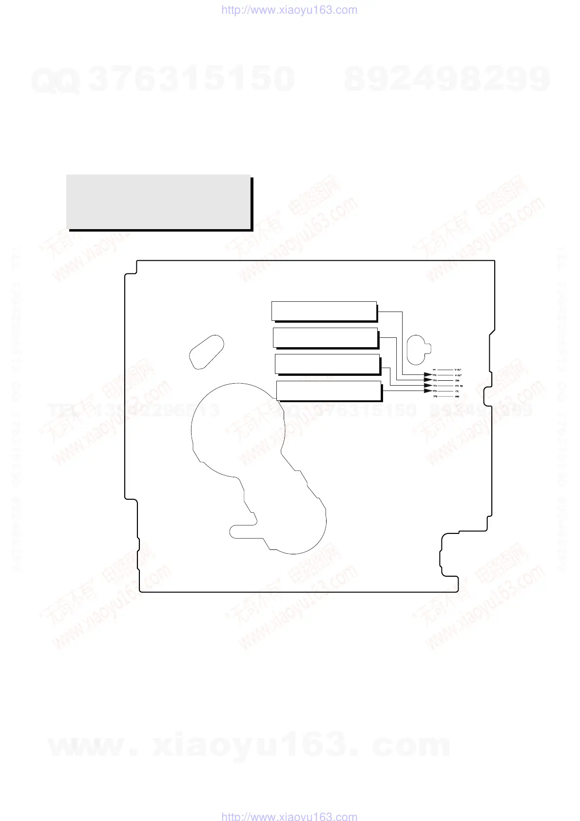
2) Intermittently short-circuit the two Test Points on Main PCB . (See Fig. 6-2)
3) Press the “0, 5” remote control buttons, then adjustment is operates automatically. (See Fig. 6-1)
4) Connect the CH-1 probe to “Envelope” the CH-2 probe to “H’D switching pulse” and then trigger to CH-1.
5) Insert the (-) driver into the X-Point adjustment hole and adjust it so that envelope waveform is maximum.
Test point: TP2 (Audio Output)
TP3 (Envelope)
TP4 (H’D S/W -Trigger)
TP5 (Control Pulse)
Fig. 6-8 Location of Test point (VCR Main PCB-Top View)
AUDIO OUTPUT
ENVELOPE
HEAD SWITCHING
CONTROL PULSE
w
w
w
.
x
i
a
o
y
u
1
6
3
.
c
o
m
Q
Q
3
7
6
3
1
5
1
5
0
9
9
2
8
9
4
2
9
8
T
E
L
1
3
9
4
2
2
9
6
5
1
3
9
9
2
8
9
4
2
9
8
0
5
1
5
1
3
6
7
3
Q
Q
TEL 13942296513 QQ 376315150 892498299
TEL 13942296513 QQ 376315150 892498299
http://www.xiaoyu163.com
http://www.xiaoyu163.com
 Loading...