6-3
2-3. SERVO SYSTEM CHECK
Unless otherwise specified, set the switches to the following
positions.
• PROGRAM switch ................................... LINE or LINE 1
• INPUT SELECT switch ............................. LINE or LINE 1
(Remote commander)
•
TAPE SPEED
switch ......................SP (Remote commander)
2-3-1. RF Switching Position/
AF Switching Position Adjustments
(MA-317 Board)
[Adjustment Purpose]
To adjust the link of the A-ch and B-ch of the tape playback outputs.
To make the unit compatible with other tapes and units. If this
specification is not satisfied, the link will appear on the screen and
the screen will be disrupted, etc.
Mode Playback
Signal Alignment tape: SP color bar portion
Measurement point CH1: Video LINE OUT
(RF switching position)
CN341 pin 1 (HF ADJ)
(AF switching position)
CH2: CN261 pin 3 (RF SWP)
Measuring instrument Oscilloscope
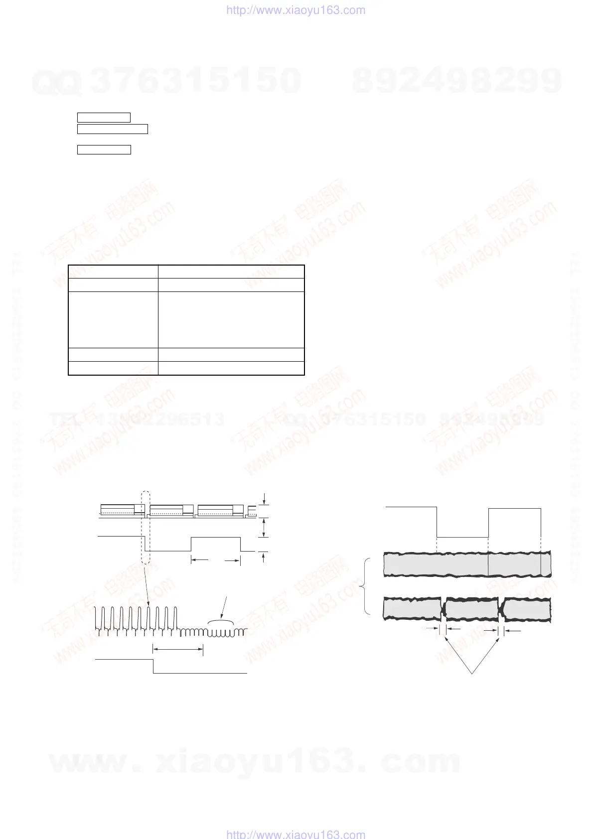
Specified value 6.5 ± 0.5H (410 ± 32 µsec)
[Adjustment Method]
1) Short-circuit between JS401 and ground for about 1 second to
activate the RF switching position adjustment mode.
2) Check that “AP” is indicated on FL display.
3) Using the channel + and – buttons, adjust to 410 ± 32 µsec (6.5
± 0.5H).
4) Press the PAUSE button. (Adjustment is over for mono models.)
5) The set goes to the AF switching position adjustment mode.
Fig. 6-2-3.
6) Check that “AH” is indicated on FL display.
7) Using the channel + and – buttons, minimize a chipped portion.
At this time, confirm that a noisy sound is not heard.
8) Press the PAUSE button.
9) Check that “AH” indication is disappeared. When it is not
disappeared, repeat from the item 1).
10) Press the STOP button.
11) Press the EJECT button.
Fig. 6-2-4.
CN261 pin
3
6.5
±
0.5H
CH1
CH2
CH1
CH2
Enlarrgement
Vertical sync. signal
Approx.
5Vp-p
Approx.
1Vp-p
V
CH2
RF SWP
CN261 pin
3
CH1
REC AFM
CN341
pin
1
OK
NG
Should be minimized
RF signal dropout
w
w
w
.
x
i
a
o
y
u
1
6
3
.
c
o
m
Q
Q
3
7
6
3
1
5
1
5
0
9
9
2
8
9
4
2
9
8
T
E
L
1
3
9
4
2
2
9
6
5
1
3
9
9
2
8
9
4
2
9
8
0
5
1
5
1
3
6
7
3
Q
Q
TEL 13942296513 QQ 376315150 892498299
TEL 13942296513 QQ 376315150 892498299
http://www.xiaoyu163.com
http://www.xiaoyu163.com