6-6
VTR
Audio line OUTPUT L/R
Audio line INPUT L/R
Audio
oscillator
Attenuator
600
Ω
Audio level
meter
or
distortion
meter
47 k
Ω
2-5. AUDIO SYSTEM ADJUSTMENT
• For the adjustment of the audio system, perform in the SP mode
if there is no special notes. Use the alignment tape.
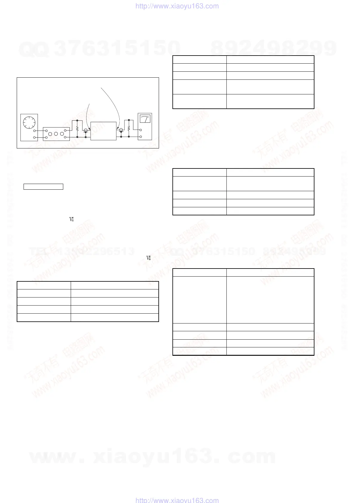
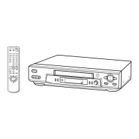
[Connecting Instruments]
Fig. 6-2-12.
• Adjust in the SP mode if there is no special indications.
• Perform the adjustment setting the switch on the following
positions.
• INPUT SELECT switch .............................. LINE or LINE 1
(Remote commander)
[Adjustment Method]
1. ACE head adjustment.....Refer to the VHS mechanical
adjustment manual
(S
MECHANISM)(9-921-647-11).
2. E-E output level check
3. Overall Output level and distortion factor check
4. Overall noise level check.
2-5-1. ACE Head Adjustment
Refer to the VHS mechanical adjustment manual
(S
MECHANISM)(9-921-647-11).
2-5-2. E-E Output Level Check
Mode E-E
Signal 400Hz, –7.5dBs : CJ570
Measurement point CJ570
Measuring instrument Audio level meter
Specified value –7.5 ± 2dBs
[Check Method]
1) Input signal of 400Hz and –7.5dBs to the CJ461 L/R.
2) Check that the audio output level is –7.5 ± 3dBs.
2-5-3. Overall Output Level and Distortion Factor
Check
Mode Self-record playback
Signal 400Hz, –7.5dBs : CJ570
Measurement point CJ570
Measuring instrument Audio level meter and Distortion
meter
Specified value Playback Level: –7.5 ± 3dBs
Distortion: 4.0% or less
[Check Method]
1) Input signal of 400Hz and –7.5dBs to the audio input.
2) Record signal.
3) Playback the recorded portion.
4) Check that the output level is –7.5 ± 3dBs.
5) Check that the distortion factor is 4.0% or less.
2-5-4. Overall Noise Level Check
Mode Self-record playback
Signal No signal (Insert a shorting plug into
the Audio LINE IN terminal)
Measurement point CJ570
Measuring instrument Audio level meter
Specified value – 45.5dBs or less
[Check Method]
1) Record.
2) Playback recorded portion.
3) Check that noise level is – 45.5dBs or less.
2-6. TUNER SYSTEM ADJUSTMENT (HiFi MODEL)
2-6-1. Separation Adjustment (MA-317 Board)
Mode E-E
Signal RF signal
Video : Color bar
white (100%) modulation
Audio : L: 400Hz, R: 2kHz
30% modulation
Electrical field:
60-80dBm/75Ω terminated
Measuring instrument Audio level meter
Measuring point LINE OUT L
Adjusting element RV731
Specified value 2kHz component minimum
[Adjustment Method]
1) Connect an audio level meter to LINE OUT L channel via HPF.
2) Feed the RF signal from RF IN terminal.
3) Adjust with RV731 so that the output level satisfies the specified
value.
w
w
w
.
x
i
a
o
y
u
1
6
3
.
c
o
m
Q
Q
3
7
6
3
1
5
1
5
0
9
9
2
8
9
4
2
9
8
T
E
L
1
3
9
4
2
2
9
6
5
1
3
9
9
2
8
9
4
2
9
8
0
5
1
5
1
3
6
7
3
Q
Q
TEL 13942296513 QQ 376315150 892498299
TEL 13942296513 QQ 376315150 892498299
http://www.xiaoyu163.com
http://www.xiaoyu163.com