Do you have a question about the Sony SLV-779HF and is the answer not in the manual?
Technical specifications for the SLV-772HF/779HF VCR, covering system, tuner, inputs/outputs, timer, and general details.
Procedure to test AC leakage from exposed metal parts to earth ground and other parts.
Explanation of how error codes are displayed and listed for troubleshooting.
Lists and explains mode codes indicating VCR operation status or errors.
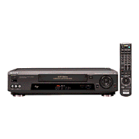
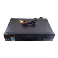
Check the received items with the VCR: remote, cables, batteries.
Table to help select the best hookup option based on TV and cable box capabilities.
Steps for setting up the VCR for Hookup 1, including RF unit switch and easy setup.
Steps for setting up the VCR for Hookup 2, including RF unit switch and easy setup.
Steps for setting up the VCR for Hookup 3, including RF unit switch and easy setup.
Steps for setting up the VCR for Hookup 4, including RF unit switch and easy setup.
Steps for setting up the VCR for Hookup 5 with DIRECTV digital satellite receiver.
Steps for setting up the VCR for Hookup 6, including RF unit switch and A/B switch setting.
Instructions for using the Auto Clock Set feature to automatically set the VCR's clock.
Step-by-step guide for manually setting the year, month, day, hour, and minutes for the clock.
Procedure to check if the VCR correctly controls the cable box or DIRECTV receiver.
Procedure for automatically presetting all receivable channels in sequence.
Steps to manually preset or disable individual channels using the VCR's tuning function.
Explanation of how the VCR Plus+ system uses PlusCode numbers for automatic recording.
Instructions on how to play a tape using the VCR's basic functions.
How to display the remaining tape length and time counter on the TV screen.
Steps for manually setting the VCR timer for recording programs when VCR Plus+ is unavailable.
Explanation of daily/weekly recording patterns and how to select them.
Instructions for automatically skipping portions of the tape while searching forward or backward.
Information on recording stereo and bilingual audio programs and selecting sound during playback.
Instructions for adjusting tracking and using the Adaptive Picture Control (APC) function.
Details on options like Auto Ant Select, Tuner Audio, Tape Select, Auto Tape Speed, and Sharpness.
Setting the RF unit and attaching external antenna connectors or UHF/VHF mixers.
Index for rear panel components and remote commander buttons with page references.
Instructions for removing the case and front panel block assembly.
Instructions for removing the rear panel.
Instructions for removing the mechanism deck and related parts.
Diagram showing internal components viewed from the top, including drum and FE head assemblies.
Diagram showing the location of the main circuit boards: MA-341, MF-316, and DM-84.
High-level block diagram showing the main functional blocks of the VCR system.
Shows the connection from the tuner block to the video processing section.
Shows the connection from the video block to the servo/system control/tuner.
Shows the connection from the tuner block to the audio processing section.
Cross-reference to the MA-341 board power supply schematic diagram.
Common notes for interpreting printed wiring boards and schematic diagrams, including symbols and abbreviations.
Schematic diagram for the video block, focusing on IC260 functions and connections.
Overall schematic diagram showing interconnections between major boards and components.
Diagrams showing the signal path for video and audio signals within the board.
Diagrams showing the signal path for audio signals within the board.
Diagrams showing the signal path for video, audio, and tuner signals.
Diagrams showing the signal path for remote control signals.
Designation of the MA-341 board section relevant to the power supply schematic.
Schematic diagram for the DM-84 board, detailing tape operation circuitry.
Designation of the MF-316 board.
Pin functions for IC160 in the system control mechanism block interface.
Pin functions for IC160 in the system control peripheral circuit interface.
Detailed description of each pin's function, I/O level, and related controls for IC160.
Continued details of IC pin functions, including signal inputs, outputs, and special functions.
Reference to VHS Mechanical Adjustment Manual for mechanical adjustments.
The recommended sequence for performing VCR adjustments: Power Supply, Servo/Video, and Audio.
Procedure to adjust tape playback output links for unit compatibility and screen integrity.
Refer to VHS mechanical adjustment manual for ACE head adjustment.
Diagram showing the location of adjustable parts on the MA-341 board (conductor side).
Exploded views showing VCR components and their part numbers for identification.
List of parts and their references for the chassis section.
List of parts and references for the first section of the mechanism deck.
List of parts and references for the second section of the mechanism deck.
List of parts and references for the third section of the mechanism deck.
Notes on standardization, stocking, and critical safety components for parts list.
List of capacitors with part numbers, descriptions, and specifications.
List of coils (inductors) with part numbers, descriptions, and specifications.
List of integrated circuits with part numbers, descriptions, and key functions.
List of resistors with part numbers, descriptions, and specifications.
List of switches with part numbers and descriptions.
List of connectors for the MF-316 board with part numbers and pin configurations.
List of hardware items like screws used in assembly.