6-3
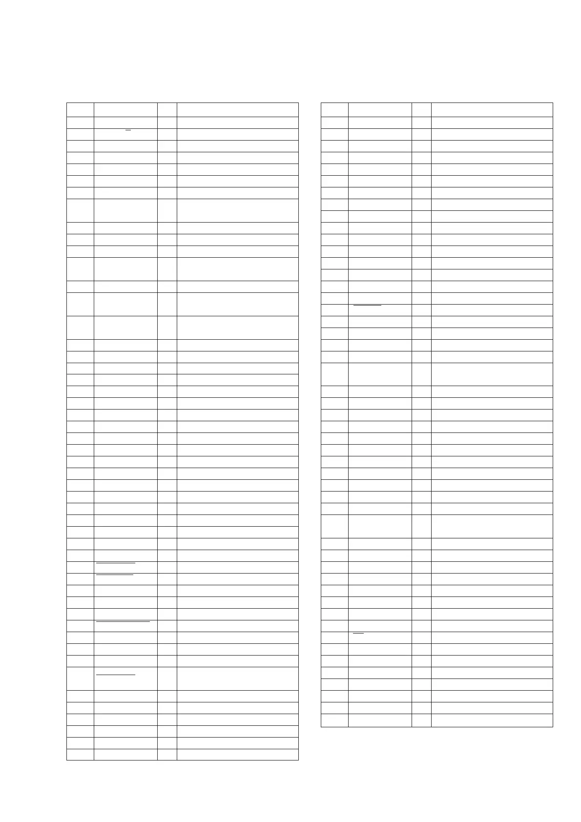
6-5. SERVO/SYSTEM CONTROL MICROPROCESSOR PIN FUNCTIONS
(MA-286 BOARD IC160)
Pin No.
1
2
3
4
5
6
7
8
9
10
11
12
13
14
15
16
17
18
19
20
21
22
23
24
25
26
27
28
29
30
31
32
33
34
35
36
37
38
39
40
41
42
43
44
45
46
47
48
49
50
Pin Name
RF SWP
AF REC P
QVD
AUTO PRESET
FE ON
REC CTL
CTL RESET
CAM 2
CAM 1
TA MUTE
SECAM DET
NT JUDGE
MESECAM
CIN (REC PRF)
AV CONT
N. C.
SW1
MODE 4
MODE 3
MODE 2
MODE 1
N. C.
PAL PLUS CONT
N. C.
N. C.
N. C.
SDA 0
N. C.
SCL 0
A MUTE
T/E LED
N. C.
N. C.
CAP STOP
FULL ERS
N. C.
N. C.
MP
ASURA RESET
VSS
XTAL
EXTAL
ASURA CS
S IN 0
S OUT 0
SCLK
N. C.
N. C.
N. C.
I/O
O
O
—
O
O
O
O
O
O
O
O
I
I
I
I
O
—
O
I
I
I
I
—
O
—
—
—
I/O
—
I/O
O
O
—
—
O
O
O
O
I
I
—
—
—
I
I
O
O
—
—
—
Function
RF switching pulse output.
“H” when HiFi audio REC.
Not used.
Quasi VD pulse output.
“H” during auto preset.
Not used.
REC CTL signal output.
Capstan current control. “H” during
slow mode.
Cam motor control.
Cam motor 9V, 12V switch.
Tuner audio mute. H: Mute
“H” when the SECAM signal is
detected.
4.43/3.58 judge input.
“H” when the MESECAM signal is
detected.
Erasing protection tab, cassette in
detection signal input.
On/Off control.
Not used.
Cam encoder signal input.
Cam encoder signal input.
Cam encoder signal input.
Cam encoder signal input.
Not used.
Not used.
Not used.
Not used.
IIC data.
Not used.
IIC clock.
“H” when audio mute.
Tape top/end sensors driver .
Not used.
Not used.
Capstan stop signal output.
Full erase control.
Not used.
Not used.
Fixed to “L”.
System reset signal.
Ground.
System clock 16MHz.
System clock 16MHz.
Servo/system control microcomputer
chip select signal.
Serial communication signal.
Serial communication signal.
Serial communication signal.
Not used.
Not used.
Not used.
Pin No.
51
52
53
54
55
56
57
58
59
60
61
62
63
64
65
66
67
68
69
70
71
72
73
74
75
76
77
78
79
80
81
82
83
84
85
86
87
88
89
90
91
92
93
94
95
96
97
98
99
100
Pin Name
SW2
AVSS
AVREF
AVDD
NTPB SW
AV ADJ
N. C.
N. C.
AF ENV
RF ENV
T SENS
S SENS
S REEL FG
T REEL FG
VSYNC
PB CTL
DRM PG
DRM FG
CAP FG
CAP RVS
CAP DA
DRM DA
CTL REC
CTL STEP
REC COUNT
N. C.
N. C.
DATA (SSB)
CLOCK (SSB)
N.C.
N. C.
CAP TRQ PWM
N. C.
N. C.
N. C.
VSS
VDD
5V
N. C.
CTL GAIN
SP
N. C.
N. C.
REC
N. C.
N. C.
STEP PLS
AF SWP
I/O
O
—
—
—
I
I
—
—
I
I
I
I
I
I
—
I
I
I
I
I
—
O
O
O
O
O
I
—
—
I/O
I/O
—
—
O
I
—
—
—
—
—
—
O
O
—
—
O
—
—
O
O
Function
Tuner select switch.
Unswitched ground.
AD port reference input UNSW 5V.
UNSW 5V.
NTSC playback switch.
Adjustment mode.
Not used.
Not used.
HiFi audio playback signal envelope.
Video playback signal envelope.
Take-up end sensor.
Supply end sensor.
Supply reel FG input.
Take-up reel FG input.
Not used.
Composite sync. signal input.
Playback CTL input.
Drum PG input.
Drum FG input.
Capstan FG input.
Not used.
Capstan reverse control “H” when
reverse.
Capstan error D/A output.
Drum PG input.
“H” : CTL is recorded.
CTL amp, STEP operation control.
Counter signal input when recording.
Not used.
Not used.
Serial communication data.
Serial communication clock.
Not used.
Not used.
PWM output for capstan torque
control.
Not used.
Not used.
Not used.
Ground.
5V.
5V.
Not used.
CTL amp gain control.
Normal audio tape speed select.
Not used.
Not used.
“H” output when recording.
Not used.
Not used.
Step pulse “H” when capstan stops.
AF switching pulse output.