7-3
2-3. SERVO SYSTEM CHECK
Unless otherwise specified, set the switches to the following
positions.
• CHANNEL switch ..................................................... LINE
•
TAPE SPEED
switch ......................................................... SP
2-3-1. RF Switching Position Adjustment
(MA-286, RP-217 Boards)
[Adjustment Purpose]
To adjust the link of the A-ch and B-ch of the tape playback outputs.
To make the unit compatible with other tapes and units. If this
specification is not satisfied, the link will appear on the screen and
the screen will be disrupted, etc.
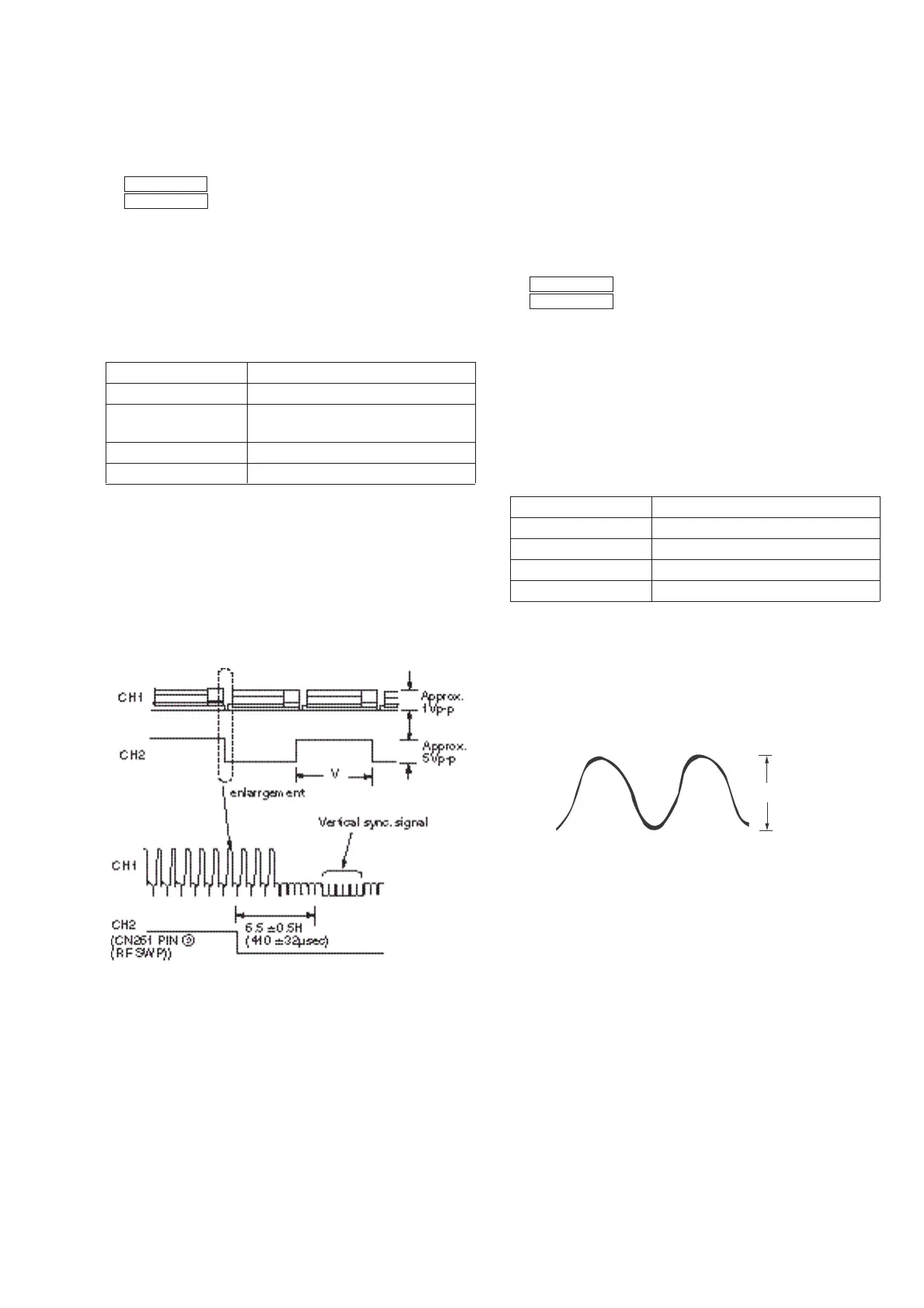
Mode Playback
Signal Alignment tape: SP color bar portion
Measurement point CH1: Video LINE OUT (EURO)
CH2: CN261 pin 2 (RF SWP)
Measuring instrument Oscilloscope
Specified value 6.5 ± 0.5H (416 ± 32 µsec)
[Adjustment Method]
1) Short-circuit between CN261 pin 5 and pin 3 on RP-217
board for about 1 second to activate the RF switching position
adjustment mode.
2) Check that “ADJ-RF” is indicated on FL display.
3) Using the channel + and – buttons, adjust to 416 ± 32µsec (6.5
± 0.5H).
4) Press the PAUSE button.
5) Press the EJECT button.
Fig. 7-2-3.
2-4. VIDEO SYSTEM CHECKS AND ADJUSTMENT
For the video system checks, follow the checking procedures given
below as a rule. The color bar video signal supplied from the pattern
generator is used as the video input signal for the video system
adjustment of the recording mode. Check that the signal satisfies
the specified value designated in the “Check of input signal” (Fig.
7-2-2)
Unless otherwise specified, set the switches to the following
positions.
• CHANNEL switch .................................................. LINE 1
•
TAPE SPEED
switch ......................................................... SP
[Checking Sequence]
1) X’tal OSC Check
2) SYNC AGC Check
3) White clip/Dark clip Check
4) Recording Y Level Check
5) Recording Chroma Level Check
6) Playback Level Check
7) VCO frequency adjustment
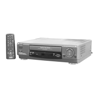
2-4-1. X’tal OSC Check (MA-286 Board)
Mode Playback
Signal Alignment tape: SP Color bar portion
Measurement point IC201 pin %•
Measuring instrument Oscilloscope and Frequency counter
Specified value 4,433,619 ± 96Hz
Note: A frequency counter should be connected through a buffer
amplifier (oscilloscope, etc.) having a high impedance and
a low capacitance.
[Check Method]
1) Check that the oscillation frequency satisfies the specified value
and that the oscillation voltage is 500 ± 200mVp-p.
Fig. 7-2-4.
500 ± 200mVp-p
4,443,619 ± 90Hz