24
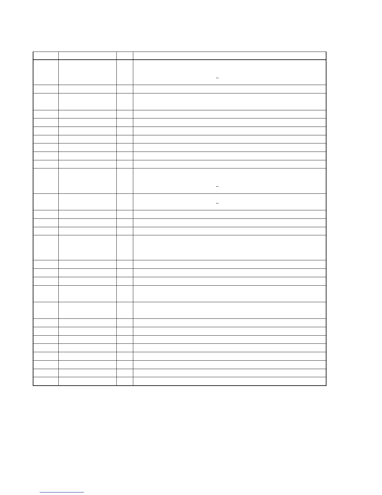
Pin Name I/O
Function
1 SDOS I
SDTO source select pin
“L”: internal ADC output, “H”: DAUX input
ORed with serial control register if P/S = “L” (Connected to ground)
2 I2C I Serial control mode select pin
3 S MUTE I
Soft mute pin
“H”: Soft mute ON, “L”: OFF
4 BCLK I/O Audio serial data clock pin
5 LRCK I/O Input/output channel clock pin
6 SDT11 I DAC1 audio serial data input pin
7 SDT12 I DAC2 audio serial data input pin
8 SDT13 I DAC3 audio serial data input pin
9 SDTO O Audio serial data output pin
10 DAUX I AUX audio serial data input pin (Connected to ground)
11 DFS I
Double speed sampling mode pin
“L”: normal speed, “H”: double speed
ORed with serial control register if P/S = “L”
12 – 13 DEM1 – DEM0 I
De-emphasis pin
ORed with serial control register if P/S = “L” (Connected to ground)
14 TVDD — Connected to digital power supply.
15 D. 5V — Digital power supply pin
16 D. GND — Digital ground pin
17 PDN I
Power-down & reset pin
When “L”, the AK4527 is powered-down and the control registers are reset to default state.
If the state of CAD0-1 changes, then the AK4527 must be reset by PDN.
18 ICKS2 I Input clock select 2 pin. (Connected to ground)
19 ICKS1 I Input clock select 1 pin. (Connected to digital power supply)
20 ICKS0 I Input clock select 0 pin. (Connected to digital power supply)
21 CAD1 I
Chip address pin
Used during the serial control mode. (Connected to ground)
22 CAD0 I
Chip address pin
Used during the serial control mode. (Connected to ground)
23 LOUT3 O Lch #3 analog output pin
24 ROUT3 O Rch #3 analog output pin
25 LOUT2 O Lch #2 analog output pin
26 ROUT2 O Rch #2 analog output pin
27 LOUT1 O Lch #1 analog output pin
28 ROUT1 O Rch #1 analog output pin
29 LIN– I Lch analog negative input pin
30 LIN+ I Lch analog positive input pin
• IC1008 AK4527 A/D, D/A CONVERTER (DIGITAL BOARD)
Pin No.