EasyManua.ls Logo

Sony STR-K890 User Manual

Sony STR-K890
60 pages
To Next Page IconTo Next Page
Page #1 background imageLoading...
Page #1 background image
SERVICE MANUAL
Sony Corporation
Home Audio Division
Published by Sony Techno Create Corporation
AEP Model
UK Model
MULTI CHANNEL AV RECEIVER
9-887-520-01
2007A16-1
© 2007.01
Ver. 1.0 2007.01
SPECIFICATIONS
STR-K890
STR-K890 is the tuner and the amplifier section
in HT-DDW890.
This receiver incorporates Dolby* Digital and Pro Logic Surround and
the DTS** Digital Surround System.
* Manufactured under license from Dolby Laboratories. “Dolby”, “Pro
Logic”, “Surround EX”, and the double-D symbol are trademarks of
Dolby Laboratories.
** “DTS” and “DTS-ES Neo:6” are registered trademarks of DTS, Inc.
“96/24” is a trademark of DTS, Inc.
— Continued on next page —
Amplifier section
Power Output
1)
Models of area code AEP, UK
Stereo mode (6 ohms, 1 kHz, THD 1%)
90 W + 90 W
Surround mode
2)
(reference) (6 ohms, 1 kHz,
THD 10%)
RMS output
FRONT:135 W
per channel
CENTER:135 W
SURROUND:135 W
per channel
SURROUND BACK:
135 W
1)
Measured under the following conditions:
2)
Reference power output for front, center, surround
and surround back speakers. Depending on the
sound field settings and the source, there may be
no sound output.
Inputs (Analog)
Inputs (Digital)
Outputs (Analog)
Reproduction frequency range:
28 – 20,000 Hz
Tone
FM tuner section
Tuning range 87.5 - 108.0 MHz
Antenna FM wire antenna
Antenna terminals 75 ohms, unbalanced
Intermediate frequency
10.7 MHz
AM tuner section
Tuning range
Models of area code AEP, UK
With 9-kHz tuning scale:
531 – 1,602 kHz
AntennaLoop antenna
Intermediate frequency
450 kHz
Video section
Inputs/Outputs
Video: 1 Vp-p, 75 ohms
COMPONENT VIDEO:
Y: 1 Vp-p, 75 ohms
P
B/CB: 0.7 Vp-p, 75 ohms
P
R/CR: 0.7 Vp-p, 75 ohms
80 MHz HD Pass Through
Area code Power requirements
AEP, UK 230 V AC, 50 Hz
SA-CD/CD/CD-R,
TV, SAT, DVD,
VIDEO 1, 3
Sensitivity: 800 mV
Impedance: 50 kohms
DVD (Coaxial) Sensitivity: –
Impedance: 75 ohms
SAT, VIDEO 2/BD
(Optical)
Sensitivity: –
Impedance: –
SA-CD/CD/CD-R
(OUT),
VIDEO 1 (AUDIO
OUT)
Vo l t age: 800 mV
Impedance: 10 kohms
SUB WOOFER Voltage: 2 V
Impedance: 1 kohm
Gain levels ±6 dB, 1 dB step
Question and Answer IconNeed help?

Do you have a question about the Sony STR-K890 and is the answer not in the manual?

Sony STR-K890 Specifications

General IconGeneral
BrandSony
ModelSTR-K890
CategoryAmplifier
LanguageEnglish

Summary

Specifications

Amplifier Section

Details power output for stereo and surround modes.

Input/Output Specifications

Lists sensitivity and impedance for analog and digital inputs/outputs.

Tuner and Video Specifications

Covers FM/AM tuning ranges and video signal characteristics.

General Information

Power Requirements and Consumption

Specifies power needs, standby consumption, and physical dimensions.

Component Replacement Notes

Provides guidance on chip components and unleaded solder usage.

Safety Related Components Warning

Highlights critical components marked for safety, requiring specific replacement parts.

Section 1 General

Front Panel Controls Overview

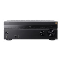
Identifies and describes the functions of front panel buttons and indicators.

Display Indicators

Signal Decoding Indicators

Details indicators for Dolby and DTS decoding modes and signal types.

Playback Channel Indicators

Explains indicators for playback channels like L, C, R, SL, SR, S, SB.

Rear Panel Connections

Digital Input/Output Section

Describes connections for optical, coaxial, and HDMI digital signals.

Component Video and Audio I/O

Details component video inputs/outputs and audio input/output jacks.

Speaker and Antenna Connections

Covers speaker terminals, subwoofer out, FM/AM antenna connections.

Remote Commander Operation

Remote Commander Functions

Explains the primary functions of the remote commander buttons.

Input Selection Buttons

Details how input buttons select and control various audio/video components.

Remote Commander Advanced Functions

Menu Navigation and Playback Controls

Describes menu access, playback, pause, stop, and track skipping functions.

Special Function Buttons

Explains buttons like OPTIONS, MENU, MUTING, VOLUME, and DISC SKIP.

Remote Commander Specific Operations

Receiver and DVD Menu Operations

Details how to navigate menus for the receiver and DVD player.

TV and Component Specific Controls

Covers TV operations, sound field selection, and remote setup.

Section 2 Test Mode

Test Mode Procedures

Outlines various test modes like Sound Field Clear, Software Version, and Key Check.

Display and System Test Modes

Describes tests for fluorescent indicators, Swap All, Shipment, and Protector modes.

DCAC Factory Test Mode

Explains the two stages of DCAC Factory Test mode for checking DSP and board functionality.

Test Mode Details

DCAC DSP Data Line Checking

Details the process and error codes for DCAC DSP data line checks.

DCAC Board Checking and VACS Control

Explains DCAC board checks and the disabling of VACS feature.

Section 3 Electrical Adjustment

Tuner Section FM Auto Stop Check

Describes the procedure for checking FM auto stop functionality using a signal generator.

Section 4 Diagrams

Schematic Diagram Notes

Provides common notes for schematic diagrams regarding component symbols and measurements.

Printed Wiring Board Notes

Explains conventions for printed wiring board diagrams, including part extraction and patterns.

Circuit Board Locations

Visually indicates the physical location of various circuit boards within the unit.

4-1. Block Diagram – Main Section

4-2. Block Diagram – Display/Power Section

4-3. Printed Wiring Board – Digital Board (Side A)

4-4. Printed Wiring Board – Digital Board (Side B)

4-5. Schematic Diagram – Digital Board (1/5)

4-6. Schematic Diagram – Digital Board (2/5)

4-7. Schematic Diagram – Digital Board (3/5)

4-8. Schematic Diagram – Digital Board (4/5)

4-9. Schematic Diagram – Digital Board (5/5)

4-10. Printed Wiring Board – Main Board

4-11. Schematic Diagram – Main Board (1/4)

4-12. Schematic Diagram – Main Board (2/4)

4-13. Schematic Diagram – Main Board (3/4)

4-14. Schematic Diagram – Main Board (4/4)

4-15. Printed Wiring Boards – Display Board, Power Key Board

4-16. Schematic Diagram – Display Board, Power Key Board

4-17. Printed Wiring Boards – Standby Board, DCDC Board

4-18. Schematic Diagram – Standby Board, DCDC Board

4-19. Printed Wiring Boards – DCAC Board, Video3 Board

4-20. Schematic Diagram – DCAC Board, Video3 Board

4-21. Printed Wiring Boards – Video Board, Headphone Board

4-22. Schematic Diagram – Video Board, Headphone Board

4-23. Printed Wiring Board – HDMI SW Board

4-24. Schematic Diagram – HDMI SW Board

IC Block Diagrams

Digital Board IC Block Diagrams

Shows block diagrams for various ICs on the digital board, including LC89056W, PCM1609APT, TC7WH157FU.

Main and Display Board IC Block Diagrams

Presents block diagrams for ICs on the main board (uPC2581V-S) and display board (TC74ACT08P).

Specific IC Block Diagrams

Details block diagrams for IC1401 PCM1803DBR and IC1101 MB90F045PF.

Display Board IC100 PT6315

HDMI SW Board IC5005 SN74LVC1G3157DCKR

Video Board IC203 NJM2595D

Video Board IC304 NJM2586AL

IC Pin Function Description

Digital Board IC1101 Pin Functions

Lists pin numbers, names, I/O, and descriptions for the MB90F045PF-G-9034-SPE1 system controller IC.

Section 5 Exploded Views

5-1. Front Panel Section Exploded View

Provides an exploded view of the front panel assembly, listing part numbers and descriptions.

5-2. Chassis Section Exploded View

Section 6 Electrical Parts List

DCAC Board Parts List

Lists capacitors, diodes, ICs, jacks, and resistors for the DCAC board.

DCDC Board Parts List

Lists capacitors, ICs, coils, and resistors for the DCDC board.

Digital Board Parts List

Lists capacitors, diodes, ICs, connectors, fuses, and resistors for the digital board.

Revision History

Revision History Details

Records the version history of the manual, including dates and descriptions of revisions.

Related product manuals