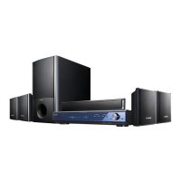
STR-KS2000
54
MAIN BOARD IC1018 MB91353APMT-G-111E1 (SYSTEM CONTROLLER)
Pin No. Pin Name I/O Description
1 SOFT_MUTE O Soft muting on/off control signal output to the stream processor "L": muting on
2 SHIFT O Shift clock signal output to the stream processor
3 DCAC ON/OFF O Mic power on/off control signal output to the mic amplifi er "H": power on
4 POWER_RESET O Reset signal output to the digital power amplifi er "L": reset
5 to 7 LAT1 to LAT3 O Serial data latch pulse signal output to the stream processor
8, 9 NO USE - Not used
10 BD3842_CLK O Serial data transfer clock signal output to the analog audio input selector
11 BD3842_DA O Serial data output to the analog audio input selector
12 POWER SD I Shut down signal input from the digital power amplifi er "L": shut down
13 SCDT O Serial data output to the stream processor
14 INT O Reset signal output to the stream processor "L": reset
15
V_ENCODER(A)_
DOWN
I Jog dial pulse input from the rotary encoder (for MASTER VOLUME) (B phase input)
16 V_ENCODER(B)_UP I
Jog dial pulse input from the rotary encoder (for MASTER VOLUME) (A phase input)
17 OVF I Over fl ow detection signal input from the stream processor "L": over fl ow
18 VSS - Ground terminal
19 VCC - Power supply terminal (+3.3V)
20 OVFW I Over fl ow detection signal input from the stream processor "L": over fl ow
21 NO USE - Not used
22 HDMI SELECT O Source selection signal output terminal
23 NO USE - Not used
24 DC_DET I DC shut down signal input terminal "L": shut down
25 NO USE - Not used
26 TUN_LAT O Latch control signal output to the tuner (FM/AM)
27 TUN_DO I PLL serial data input from the tuner (FM/AM)
28 NO USE - Not used
29 CEC OUT O CEC serial data output to the HDMI OUT connector
30 HDMI_ERR I Error mute signal input from the HDMI section
31 TUNER LED O LED drive signal output of the TUNER indicator "H": LED on Not used
32 TV LED O LED drive signal output of the TV indicator "H": LED on Not used
33 SACD LED O LED drive signal output of the SA-CD/CD indicator "H": LED on Not used
34
HDMI REG CTL
O Power on/off control signal output terminal for the HDMI section "H": power on
35 TC74HC135_B O Data selection signal output terminal
36 TC74HC135_A O Data selection signal output terminal
37 DIR XSTATE I Source clock selection monitor input from the digital audio interface receiver
38
DIR_XMODE (RESET)
O System reset signal output to the digital audio interface receiver "L": reset
39 DIR_CK_SEL O Output clock selection signal output to the digital audio interface receiver
40 VSS - Ground terminal
41, 42 NO USE - Not used
43 VSS - Ground terminal
44 VCC - Power supply terminal (+3.3V)
45 DIR_CLK O Serial data transfer clock signal output to the digital audio interface receiver
46 DIR_CE(LAT) O Chip enable signal output to the digital audio interface receiver
47 DIR D1 O Serial data output to the digital audio interface receiver
48 DIR D0 I Serial data input from the digital audio interface receiver
49 DIR ERROR I PLL lock error signal and data error fl ag input from the digital audio interface receiver
50 FSRATE I Serial data input terminal
51 NMIX I Non Maskable Interrupt signal input terminal
52 MD2 I CPU operation mode setting signal input terminal "H": fl ash programming
53, 54 MD1, MD0 I
CPU operation mode setting signal input terminal "L": fl ash programming Not used
55 INIT I Reset signal input terminal
56 VCC - Power supply terminal (+3.3V)
57 12.5MHz O Main system clock output terminal (12.5 MHz)
58 12.5MHz I Main system clock input terminal (12.5 MHz)
59 VSS - Ground terminal
w
w
w
.
x
i
a
o
y
u
1
6
3
.
c
o
m
Q
Q
3
7
6
3
1
5
1
5
0
9
9
2
8
9
4
2
9
8
T
E
L
1
3
9
4
2
2
9
6
5
1
3
9
9
2
8
9
4
2
9
8
0
5
1
5
1
3
6
7
3
Q
Q
TEL 13942296513 QQ 376315150 892498299
TEL 13942296513 QQ 376315150 892498299
http://www.xiaoyu163.com
http://www.xiaoyu163.com