13
Location and Function of Parts
Chapter 1 Overview
For information about the PARALLEL REMOTE menu,
see “
[D]
System Configuration – SYSTEM
CONFIGURATION Menu” on page 43.
To switch each function between on and off or between
enable and disable, change pin connections in the
following way.
ON or enabled: Short each pin and pin 9 together.
OFF or disabled: Leave each pin open.
f
SERVICE terminal (male, D-sub 9-pin)
This connector is for use by service personnel only.
g NETWORK switch
Set to LAN for the network connections. Set to PEER TO
PEER when the monitor is connected directly to the LAN
(10/100) connector of the BKM-15R (1 to 1 connection).
h LAN (10/100) connector (10BASE-T/100BASE-TX)
Connect to the network by using a 10BASE-T/100BASE-
TX LAN cable (shield type, optional) or to the LAN (10/
100) connector of the BKM-15R. Or connect to the LAN
(10/100) connector of the BKM-15R by using the SMF-
700.
CAUTION
• When an optional LAN cable is connected, use a shield
type cable to prevent miss-operation due to noises. Also,
to directly connect the monitor to the LAN (10/100)
connector of the BKM-15R (NETWORK switch is set to
PEER TO PEER) (1 to 1 connection), use a straight
(shield type) cable.
• For safety, do not connect the connector for peripheral
device wiring that might have excessive voltage to this
port.
Follow the instructions for this port.
• The connection speed may be affected by the network
system. This unit does not guarantee the communication
speed or quality of 10BASE-T/100BASE-TX.
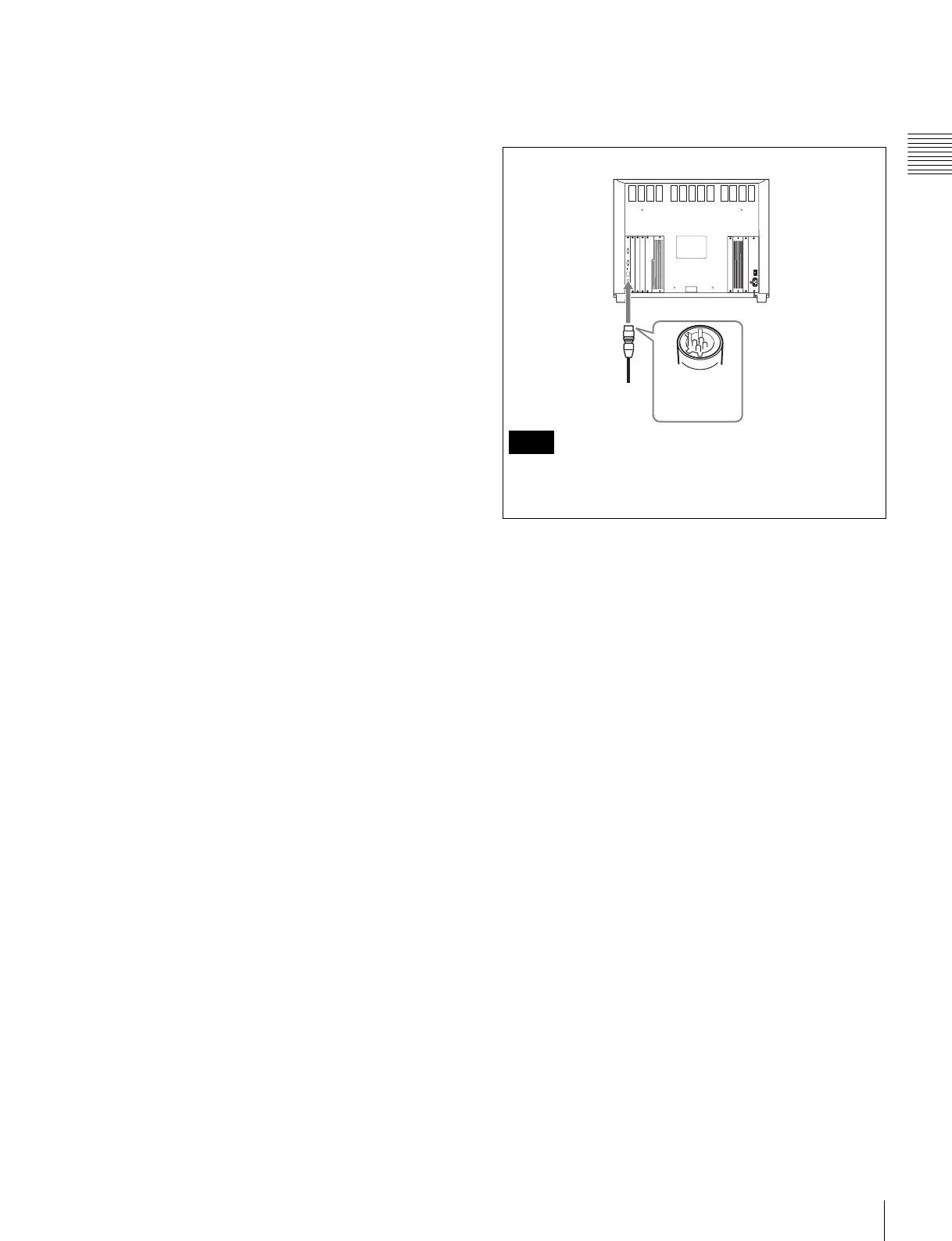
i DC 5V OUT connector (female)
Supplies the DC power for the BKM-15R.
Connect to the DC 5V IN connector of the BKM-15R with
the SMF-700.
Be sure to plug the male connector of the cable into the
DC 5V OUT connector on the monitor.
Note
Plug the male
connector into
the monitor.