46
[E] Installation Settings – INSTALLATION SETTINGS Menu
Chapter 2 Menu
ON: Displayed.
OFF: Not displayed.
POSITION: Select the display position for the
channel name.
TOP LEFT (default), TOP CENTER, TOP RIGHT,
BOTTOM LEFT, BOTTOM CENTER, BOTTOM
RIGHT
[D6] PASSWORD... menu
Set the password for the menu
Enter four characters. Default setting is “9999”.
CHANGE PASSWORD...: Change the password.
k[D61]
APPLY PASSWORD...: Assign the password to a
menu item. k[D62]
[D61] CHANGE PASSWORD... menu
Change the password.
ENTER NEW PASSWORD: Enter a new password
with the number button and press the ENTER
button. k[D611]
[D611] CHANGE PASSWORD menu
Create a new password.
RE-ENTER PASSWORD: Enter the new password
again and press the ENTER button. The password
is registered.
To change it, press the MENU button.
[D62] APPLY PASSWORD... menu
Select whether or not to apply the password to each menu.
PICTURE ADJ: Select YES or NO.
COLOR TEMP ADJ: Select YES or NO.
INPUT CONFIGURATION: Select YES or NO.
SYSTEM CONFIGURATION: Select YES or NO.
INDIVIDUAL ITEMS...: Display the items of the
SYSTEM CONFIGURATION menu. k[D621]
INSTALLATION SETTINGS: Select YES or NO.
FILE MANAGEMENT: Select YES or NO.
CONTROLLER: Select YES or NO.
KEY PROTECT: Select YES or NO.
[D621] APPLY PASSWORD menu
Select whether or not to apply the password to the
SYSTEM CONFIGURATION menu.
NETWORK: Select YES or NO.
PARALLEL REMOTE: Select YES or NO.
POWER: Select YES or NO.
BLANKING SETTINGS: Select YES or NO.
ON SCREEN SET: Select YES or NO.
GAMMA SW: Select YES or NO.
[D7] MAINTENANCE... menu
The menu for the maintenance personnel is displayed.
[E] Installation Settings
– INSTALLATION
SETTINGS Menu
Overview
Initial settings of geometry, convergence, etc. are adjusted
from this menu.
The following are adjusted.
• Correcting the shift of beam landing caused by the
earth’s magnetism (LANDING ADJUST... menu)
• Adjusting the position and size of the picture and
convergence (ALIGNMENT... menu )
• Adjusting the color unevenness of the CRT
(DIGITAL UNIFORMITY ADJ... menu)
Perform digital uniformity adjustment after beam landing
adjustment has been completed.
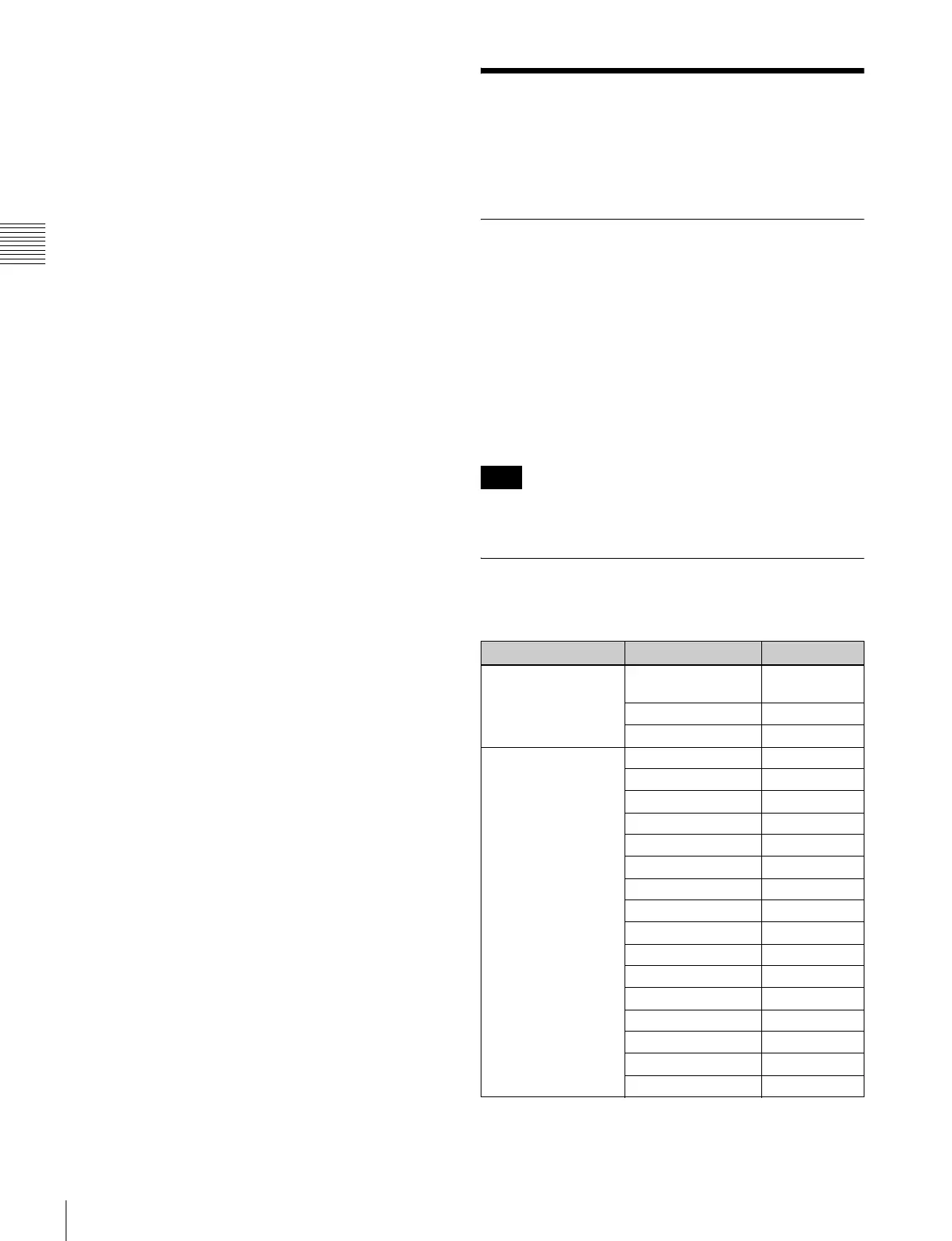
Structure of the INSTALLATION
SETTINGS Menu
Note
Level 1 Level 2 Level 3
LANDING ADJUST...
[E1]
MANUAL ADJUST...
[E11]
SIGNAL
AUTO ADJUST [E12]
ALIGNMENT... [E2] ROTATION
H PHASE
V CENTER
H SIZE
V SIZE
SUB CONTRAST
H PIN
H PIN BAL
H CORNER PIN
H CORNER S
H KEY
H KEY BAL
V STATIC CONV
V CONV TOP
V CONV BOT
H STATIC CONV