47
[E] Installation Settings – INSTALLATION SETTINGS Menu
Chapter 2 Menu
Setting Lists in the INSTALLATION
SETTINGS Menu
This section explains the setting lists displayed in the
menu.
How to read the setting lists
• For purposes of explanation, each setting list is preceded
by a menu number. These numbers are not displayed on
the screen.
For more information on menu numbers, see “About menu
numbers” on page 26.
• The arrow mark (k) refers you to another setting list
that appears after you make a setting, or to an operation
that is to be carried out as a result of a setting.
[E] INSTALLATION SETTINGS menu
LANDING ADJUST...: Set the initial value of
landing, alignment, signal level adjustment, etc.
k[E1]
ALIGNMENT...: Adjust the position and size of the
picture and convergence. k[E2]
DIGITAL UNIFORMITY ADJ...: Adjust the color
unevenness of the CRT. k[E3]
[E1] LANDING ADJUST... menu
Set the initial value of landing, alignment, signal level
adjustment, etc.
MANUAL ADJUST...: Adjust with the MANUAL
knobs. k[E11]
SIGNAL: Select the white signal to be used for
adjustment.
EXT: Use an external input signal. Input the
appropriate signal (default).
INT: Use an internal white signal.
AUTO ADJUST: Automatically adjust using the
Sony BKM-14L Auto Setup Probe (default).
k[E12]
[E11] MANUAL ADJUST... menu
Select the rough or fine adjustment of beam landing. First
perform the rough adjustment, then proceed to fine
adjustment.
DIRECTION: Adjust the beam landing shift
approximately by selecting the direction in which
the monitor is facing.
Display the white signal and select the direction
using the UP/DOWN buttons or PHASE knob to
where the white is most uniform on the screen.
NORTH, NORTH EAST, EAST (default), SOUTH
EAST, SOUTH, SOUTH WEST, WEST or
NORTH WEST
FINE ADJUST: Adjust the beam landing shift finely
at each adjustment point on the screen.
Display the white signal, select the adjustment
point on the screen, and adjust the white at the
selected point as uniformly as possible using the
UP/DOWN buttons or PHASE knob.
NS: Correct the beam landing shift at the top center
and bottom center of the screen simultaneously
(default setting is 100).
TOP LEFT: Correct the beam landing shift at the
top left of the screen (default setting is 100).
TOP RIGHT: Correct the beam landing shift at the
top right of the screen (default setting is 100).
BOTTOM LEFT: Correct the beam landing shift
at the bottom left of the screen (default setting is
100).
BOTTOM RIGHT: Correct the beam landing
shift at the bottom right of the screen (default
setting is 100).
RESET: Reset the beam landing data at all the five
points above to the center.
[E12] AUTO ADJUST menu
Display when AUTO ADJUST is selected.
The following message appears.
SET PROBE ON CURSOR
Attach the probe on the cursor to start adjusting.
To cancel the adjustment
Press the MENU button.
[E2] ALIGNMENT... menu
Adjust the position size or geometry of the picture or
convergence with the UP and DOWN buttons or PHASE
knob.
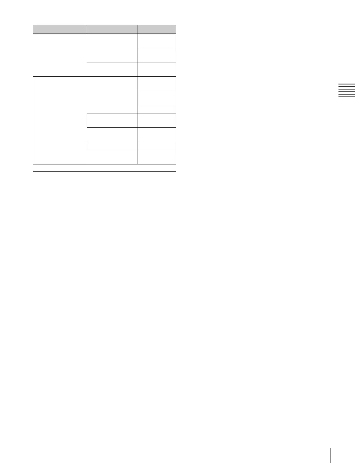
ALIGNMENT... [E2] CONV FINE
ADJUST... [E21]
MANUAL
ADJUST [E211]
RESTORE
FACTORY DATA
RESTORE FACTORY
DATA
DIGITAL UNIFORMITY
ADJ... [E3]
MANUAL... [E31] MANUAL
ADJUST [E311]
CURSOR H
SIZE
V SIZE
AUTO FULL POINTS
ADJ [E32]
AUTO ONE POINT
ADJ [E33]
SIGNAL
RESTORE FACTORY
DATA
Level 1 Level 2 Level 3