an internally generated reference voltage to determine
the current flow
to
the control winding
of
trans-
former T4 (PRT-I). T4
is
a cross transformer with
the mutual inductance between the primary and
secondary windings controlled
by
the current through
a perpendicular winding. Consequently, the fre-
quency and voltage
of
a resonant circuit, CIS and T5,
is varied. The
output
from the secondary of
T5
is
rectified and filtered
to
provide +145 V
DC
(GDM-
1602: 120 V DC).
+B
over voltage is detected by
IC51 and opens
the
AC
primary input lines
via
relay
RY51. The low voltage circuit (IC52) operates in
a similar manner.
3-6. H BOARD
The following operator control VRs are mounted
on
the
H board:
V CENT
(RVI)
....
raster vertical position
adjustment
H STAT (RV2)
.....
horizontal static conver-
V STAT (RV3)
...
f)
CONT (RV4)
...
3-7. J BOARD
gence adjustment
vertical static conver-
gence adjustment
display contrast
(intensity)
An LED indicator showing
that
the power supplis
"on"
is
mounted
on
the J board.
3-8. L BOARD
3·8-1. Composition
The L board consists
of
a semi-dynamic convergence
compensation circuit and a quadrapole coil drive
circuit for dynamic focus compensation (beam spot
shaping).
3-8-2. Modulated Waveform Generator
Four
types
of
modulated vertical rate parabolic
waveforms are generated for convergence and dynam-
ic focus controls.
Inverter ICI
(1/2)
receives the vertical rate parabolic
wave from the D board and generates an inverted
parabolic wave
to
be used
at
RV2 and RV7. A clamp
circuit composed
of
Q I and Q2 also receives the
parabolic wave from the D board and clamps the
middle portion
of
the
wave
to
ground potential. This
clamped wave is
input
to
IC4
at
pin
@)
and an iverted
clamped wave from ICI
(2/2)
is
input
to
IC4
at
pin
q).
Transistor
Q3
receives HD pulses from the D board
and
generates a vertical period ramp signal across C4,
that
is
input
to
zero-crossing comparator IC2 (1/2).
A 50% duty cycle square wave
is
output
from IC2
(1/2)
and drives switcher IC4.
Asa
result IC4
outputs
the following four wave-.
formes:
3-6
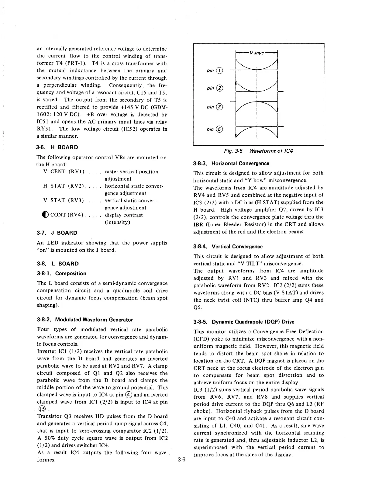
pin
CD
pin
®
pin
0
pin
®
r--
V
snyc--j
~.~
U
VM
I 1 I
V"'J
Fig. 3-5 Waveforms
of
IC4
3·8·3. Horizontal Convergence
This circuit
is
designed
to
allow adjustment for
both
horizontal static and
"Y
bow"
misconvergence.
The waveforms from IC4 are amplitude adjusted by
RV4 and RV5 and combined at
the
negative input
of
IC3
(2/2)
with a
DC
bias (H STAT) supplied from the
H board. High voltage amplifier Q7, driven by IC3
(2/2), controls the convergence plate voltage thru the
IBR (Inner Bleeder Resistor) in the CRT and allows
adjustment
of
the
red and the electron beams.
3·8-4. Vertical Convergence
This circuit is designed
to
allow adjustment of
both
vertical static and
"V
TILT" misconvergence.
The
output
waveforms from IC4 are amplitude
adjusted by RVI and RV3 and mixed with the
parabolic waveform from RV2. IC2 (2/2) sums these
waveforms along with a
DC
bias (V STAT) and drives
the neck twist coil (NTC) thru buffer amp Q4 and
Q5.
3-8·5. Dynamic Ouadrapole (DOP) Drive
This monitor utilizes a Convergence Free Deflection
(CFD) yoke
to
minimize misconvergence with a non-
uniform magnetic field. However, this magnetic field
tends
to
distort the beam spot shape in relation
to
location
on
the CRT. A
DQP
magnet
is
placed on the
CRT neck at
the
focus electrode
of
the electron gun
to
compensate for beam spot distortion and
to
achieve uniform focus
on
the
entire display.
IC3
(1/2)
sums vertical period parabolic wave signals
from RV6, RV7, and RV8 and supplies vertical
period drive current
to
the DQP
thru
Q6 and
L3
(RF
choke). Horizontal flyback pulses from the D board
are input
to
C40 and activate a resonant circuit con-
sisting
of
LI,
C40, and C41.
As
a result, sine
wave
current synchronized with the horizontal scanning
rate
is
generated and,
thru
adjustable inductor L2,
is
superimposed with the vertical period current
to
improve focus
at
the sides
of
the display.
 Loading...