4
GDM-C520
Setup
1
Connecting your monitor to your computer
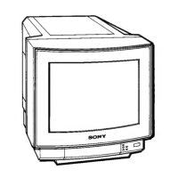
x Connecting to an IBM PC/AT or compatible computer
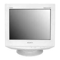
x Connecting to a Macintosh or compatible computer
No adapter is required for the later model G3/G4. Earlier Macintosh
computers may require an adapter (not supplied).
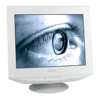
x Connecting to a second computer
Notes
• Do not touch the pins of the video signal cable connector.
• Check the alignment of the HD15 connector to prevent bending the pins
of the video signal cable connector.
To select the input signal
You can connect two computers to this monitor using the two HD15
connectors. To select one of the two computers, use the INPUT
switch. The selected connector appears on the screen for 3 seconds.
Note
If no signal is input to the selected connector, NO SIGNAL appears on the
screen. After a few seconds, the monitor enters the power saving mode. If
this happens, switch to the other connector.
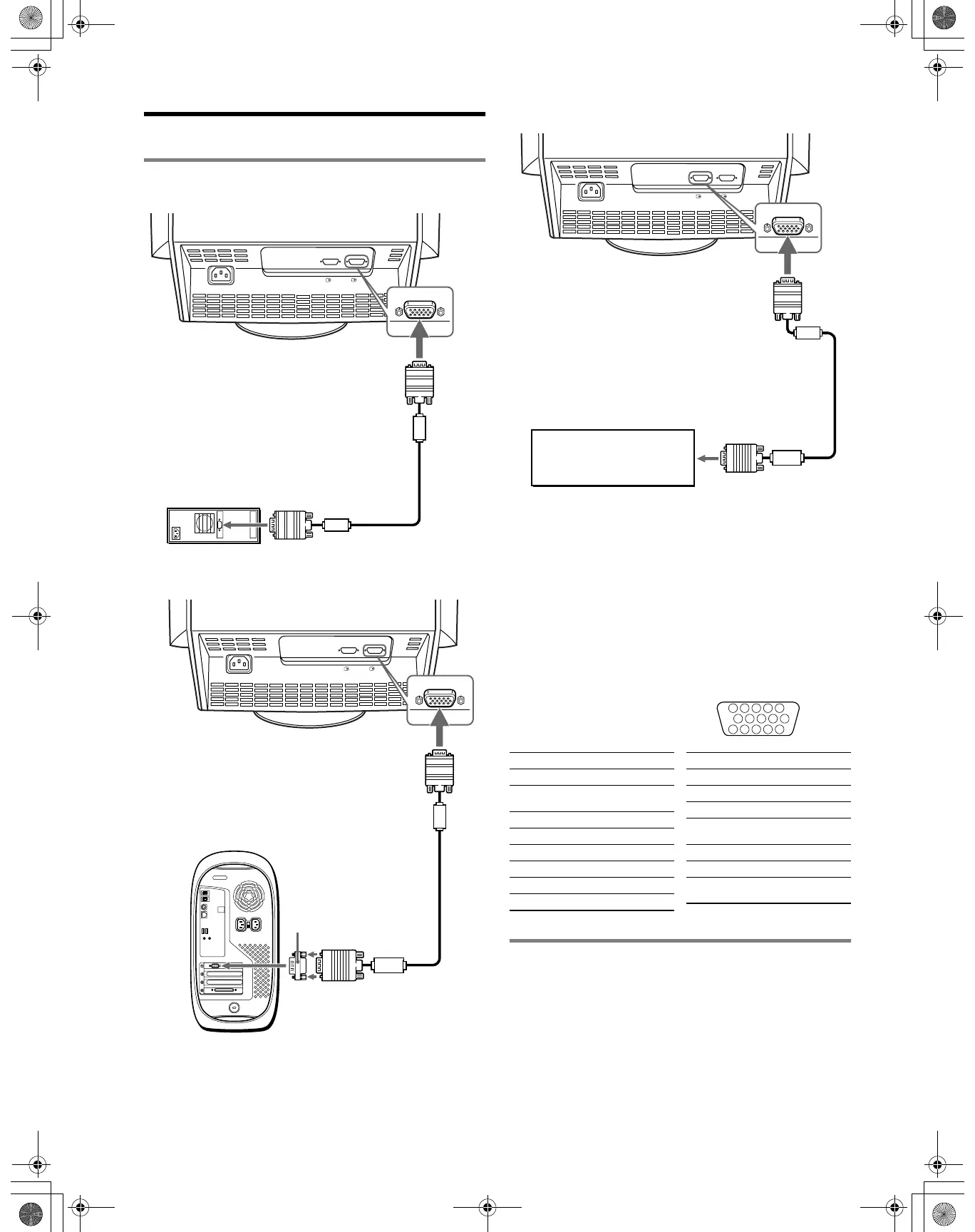
HD15 input connectors
* DDC (Display Data Channel) is a standard of VESA.
2 Turning on the monitor and computer
1 Connect the power cord to the monitor and press the
! (power) switch to turn on the monitor.
2 Turn on the computer.
No need for specific drivers
This monitor complies with the “DDC” Plug & Play standard and
automatically detects all the monitor’s information. No specific driver
needs to be installed to the computer.
The first time you turn on your PC after connecting the monitor, the setup
Wizard may appear on the screen. In this case, follow the on-screen
instructions. The Plug & Play monitor is automatically selected so that you
can use this monitor.
AC IN
2
1
video signal cable
(supplied)
IBM PC/AT or compatible
computer
to HD15
to video output
AC IN
2
1
to HD15
video signal cable
(supplied)
to video output
Macintosh or compatible computer
Macintosh adapter
(not supplied)
AC IN
2
1
Refer to the preceding
examples to connect your
computer.
video signal cable
(not supplied)
to HD15
5 4 3 2
1
678910
1112131415
Pin No. Signal
1Red
2 Green (Sync on
Green)
3Blue
4 ID (Ground)
5 DDC Ground*
6 Red Ground
7 Green Ground
8 Blue Ground
9 DDC + 5V*
10 Ground
11 ID (Ground)
12 Bi-Directional
Data (SDA)*
13 H. Sync
14 V. Sync
15 Data Clock
(SCL)*
Pin No. Signal
01US01COV-UC.book Page 4 Wednesday, July 3, 2002 10:07 AM