– 3 –
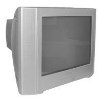
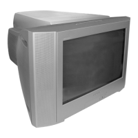
KV-HS29M61/M90/M91, HS34M61/M90/M91, HS38M61/M90/M91
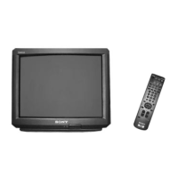
RM-997
TABLE OF CONTENTS
Section Title Page
SELF DIAGNOSIS FUNCTION .................................. 4
1. DISASSEMBLY
1-1. Rear Cover Removal .............................................. 8
1-2. Speaker Box Removal ............................................ 8
1-3. Chassis Assy Removal ............................................. 8
1-4. Service Position ....................................................... 9
1-5. DC Board Removal.................................................. 9
1-6. J Board Removal ...................................................... 9
1-7. D Board Removal .................................................. 10
1-8. A, A1, and E Boards and B4 Block Removal ...... 10
1-9. H1, H2, MS2, and F2 Boards Removal ................ 11
1-10. Picture Tube Removal (1) ...................................... 11
1-11. Picture Tube Removal (2) ...................................... 12
1-12. Harness Ranning .................................................... 13
2. SET-UP ADJUSTMENTS
2-1. Beam Landing Adjustment .................................... 15
2-2. Convergence Adjustment....................................... 16
2-3. Focus Adjustment .................................................. 18
2-4. Neck Assy Twist Adjustment ................................. 18
2-5. G2 (Screen) and White Blance Adjustments ......... 19
3. CIRCUIT ADJUSTMENTS
3-1. Adjustments with Commander .............................. 20
3-2. Adjustment Method ............................................... 21
3-3. Picture Quality Adjustments .................................. 35
3-3-1. Preparation ......................................................... 35
3-3-2. NTSC Video Input ............................................. 36
3-3-3. NTSC RF Input ................................................. 36
3-3-4. PAL Video Input ................................................ 37
3-3-5. PAL RF Input ..................................................... 37
Section Title Page
4. SAFETY RELATED ADJUSTMENTS
4-1. HV Regulation Adjustment .................................... 38
4-2. HV Hold-down Adjustment ................................... 38
4-2-1. HV Protector Adjustments ................................ 38
4-2-2. HV Protector Check ......................................... 38
4-3. +B Max Voltage Confirmation ............................... 39
4-4. +B OVP Confirmation ........................................... 39
5. DIAGRAMS
5-1. Block Diagrams ...................................................... 40
5-2. Circuit Boards Location ......................................... 56
5-3. Schematic Diagrams ............................................... 57
5-4. Semiconductors .................................................... 124
6. EXPLODED VIEWS
6-1. Picture Tube .......................................................... 128
6-2. Chassis .................................................................. 130
6-3. Packing Materials ................................................. 132
7. ELECTRICAL PARTS LIST................................... 133
 Loading...