'VM'6041QM I
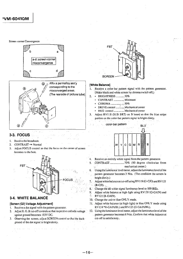
Screen-corner Convergence
3-3. FOCUS
I. Receivethebroadcast.
I
Affix a permalloy ass'y
corresponding to the
miscorwerged areas.
/ (The rears1de of picture tube)
2. CONTRAST- Nonna!
1 Adjust FOCUS control so that the focLJs on the center of screen
becomes to the best.
FBT
3-4. WHITE BALANCE
[Screen (G2) Voltage Adjustment]
FOCUS
!. Receive a dot signal with the pattern generator.
2. Adjust R. G. B cut-off controls
so that respective cathode voltage
against ground becomes I 03V DC.
3. Observing the screen, adjust SCREEN control so that the back-
ground of the dot signal is bright dimly.
FBT
SCREEN
(White Balance}
1. Recejve a color-bar pattern signal with the pattern generator.
(Make black and white screen by chroma switch off.)
2. • BRIGHTNESS ........... 50%
CONTRAST .............. Minimum
• CHROMA ... . ..... 50%
• DRIVEcontrol ........... Mechanicalcenter
• BKG control ............ Mechanical center
3. Adjust RV! 18 (SUB BRT) on B board so that the blue stripe
portion on the color-bar pattern signal is bright dimly.
color-bar pattern
BLU
4. Receive an entirely white signal from the pattern generator.
5. CONTRAST .................... 70% (90 degree clockwise from
mechanical center.)
6. Using the luminance level meter, adjust the luminancelevelof1he
pattern generator becomes 3 Nits. (The condition the screen
is
bright dimly.)
7. Adjust white balanceatcut-off using RVl 19 (G-C/0) and RV] 21
(B-C/0).,
8. Change th'e all-white signal luminance level to 100 IREs.
9. Adjust white balance at high-light using RV!20 (G-GAIN) and
RV121 (B-GAIN).
10. Change the unit to blue ONLY mode.
11. Adjust white balance (at high-light) m blue ONLY
mcx!e using
RVJ24*R-GAIN/BL)and RV125 (G-GAJN/BL).
-12. Using the luminance level meter, adjust the luminance level of the
pattern generator becomes 8
Nits. Confirm that white balance at
cut-off is satisfactory ..
-16-