>VM-6041OM I
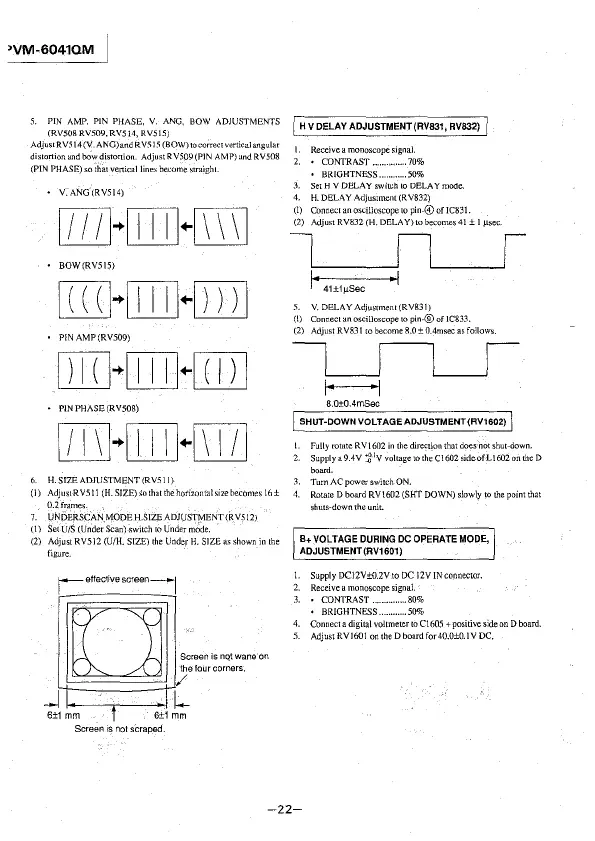
5. PIN AMP. PIN PHASE, V. ANG, BOW ADJUSTMENTS
(RV508 RV509, RV514, RV5l5)
AdjustRV514 (V. ANG)and R V5 I 5 (BOW) to correct vertical angular
distortion and bow distortion. Adjust RY509 (PIN AMP) and RV508
(PIN PHASE) so that vertical lines become straight.
V. ANG (RY514)
[D]-{OJ}-ITTI]
BOW(RVSIS)
[ill]-{[IJ}-[ITI]
P!N AMP (RV509)
[I]]~[JJJ}-[ill
PlN PHASE (RV508)
6. H. SIZEADJUSTMENT(RV51 l)
(I) AdjustRV51 l (H.SJZE)Sothatthehorizontalsizebecomes 16±
0.2frames.
7. UNDERSCAN MODE H.SIZE ADJUSTfy'IENT(RY512J
(1) Set U/S (Under Scan) switch to Under
m0de.
(2) Adjust RV5l2 (U/H. SIZE) the Under H. SIZE as shown in the
figure.
r-effective screen-1
[]
Screen is nqtwaneon
the four corners.
/
_Jc+1-----i-c1 l
6±1 mm t 6±1 mm
Screen is not scraped.
I H V DELAY ADJUSTMENT(RV831, RV832) /
I. Receive a monoscope signal.
2. • CONTRAST .. . ..... 70%
, BRIGHTNESS ......... 50%
3. Set H V DELAY switch to DELAY mode.
4. H.DELAYAdjustment(RY832)
(I) Connect an oscilloscope to pin-© of IC831.
(2) AdjustRY832
(H. DELA Y)tobecomes41 ± I µsec.
~
] • 41±1µSec • I
5. V. DELAYAdjustment(RY831)
(!) Connect an oscilloscope to pin-® of !C833.
(2) Adjust R Y831 to become 8.0 ± 0.4msec as follows.
L__JL___J
1---1
8.0±0.4mSec
SHUT~DOWN VOLT AGE ADJUSTMENT (RV1602)
l. Fully rotate RV 1602 in the direction that does not shut-down.
2. Supplya9.4Y
j/·
1
V voltagetotheC1602sideofL\602onthe D
board.
3. Tum AC power switch ON.
4.
Rotate D board RV\602 (SHT DOWN) slowly to the point that
shuts-down the
unit.
B+ VOLTAGE DURING DC OPERATE MODE,
ADJUSTMENT (RV1601)
1. Supply DC12V±0.2V to DC l2VIN connector.
2. Receive a monoscope signal.
3. • CONTRAST .. . ........ 80%
• BRIGHTNESS .......... 50%
4. Connect a digital voltmeter to C1605 + positive side on D board.
5. AdjustRVl601 ontheDboardfor40.0±0.IYDC.
-22-