1
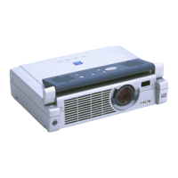
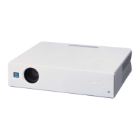
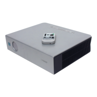
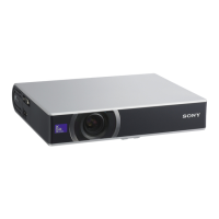
VPL-CS5/CX5
Table of Contents
1. Service Information
1-1. Board Layout...............................................................................................1-1
1-2. Disassembly ................................................................................................1-2
1-2-1. Top Panel Assy Removal ...........................................................1-2
1-2-2. Side Panel Assy and L, NR, H2, Q Boards Removal ................1-2
1-2-3. Power Block (Lamp) Removal...................................................1-3
1-2-4. DC Fan Removal ........................................................................1-3
1-2-5. Lens Gear Removal ....................................................................1-4
1-2-6. Speaker Assy and DC Fan (Sirocco) Removal .........................1-4
1-2-7. C Board Removal .......................................................................1-5
1-2-8. MSC and MS (VPL-CX5) Boards Removal ..............................1-5
1-2-9. GA and GB Boards Removal .....................................................1-6
1-2-10. Optics Block Assy and Lamp Assy Removal ............................1-7
1-2-11. PS Com Aperture and In-polarizer (R), (G), (B) Removal ........1-8
1-2-12. Lens Projection Assy and Lamp Duct Assy Removal ...............1-9
1-2-13. Prism Block Assy and
Out-pre-polarizer (R), (G), (B) Removal .................................1-10
1-2-14. DC Fan (Sirocco) and V Board Removal ................................1-11
1-2-15. Adjustor Unit Removal ............................................................ 1-11
1-2-16. Extension Board and Extension Connectors ............................1-12
1-2-17. Extension Board and Extension Connectors Connection.........1-13
1-2-18. Warning on Power Connection ................................................1-14
2. Electrical Adjustments
2-1. Preparation ..................................................................................................2-1
2-1-1. Required Equipment...................................................................2-1
2-1-2. Optical Unit Adjustment ............................................................2-1
2-1-3. How to Enter the Factory Mode .................................................2-2
2-2. V COM Adjustment ....................................................................................2-2
2-3. Initial Values of Adjustment Items ............................................................. 2-3
2-4. Service Know-How .....................................................................................2-8
2-4-1. When the Prism Block Is Replaced............................................2-8
2-4-2. When the C Board Is Replaced .................................................. 2-8
2-5. White Balance Adjustment .........................................................................2-8
2-5-1. HIGH Mode of INPUT-A ..........................................................2-8
2-5-2. LOW Mode of INPUT-A ...........................................................2-9
2-5-3. HIGH Mode of VIDEO..............................................................2-9
2-5-4. LOW Mode of VIDEO...............................................................2-9
2-6. Memory Structure .....................................................................................2-10

 Loading...