ZS-RS70BT/RS70BTB
11
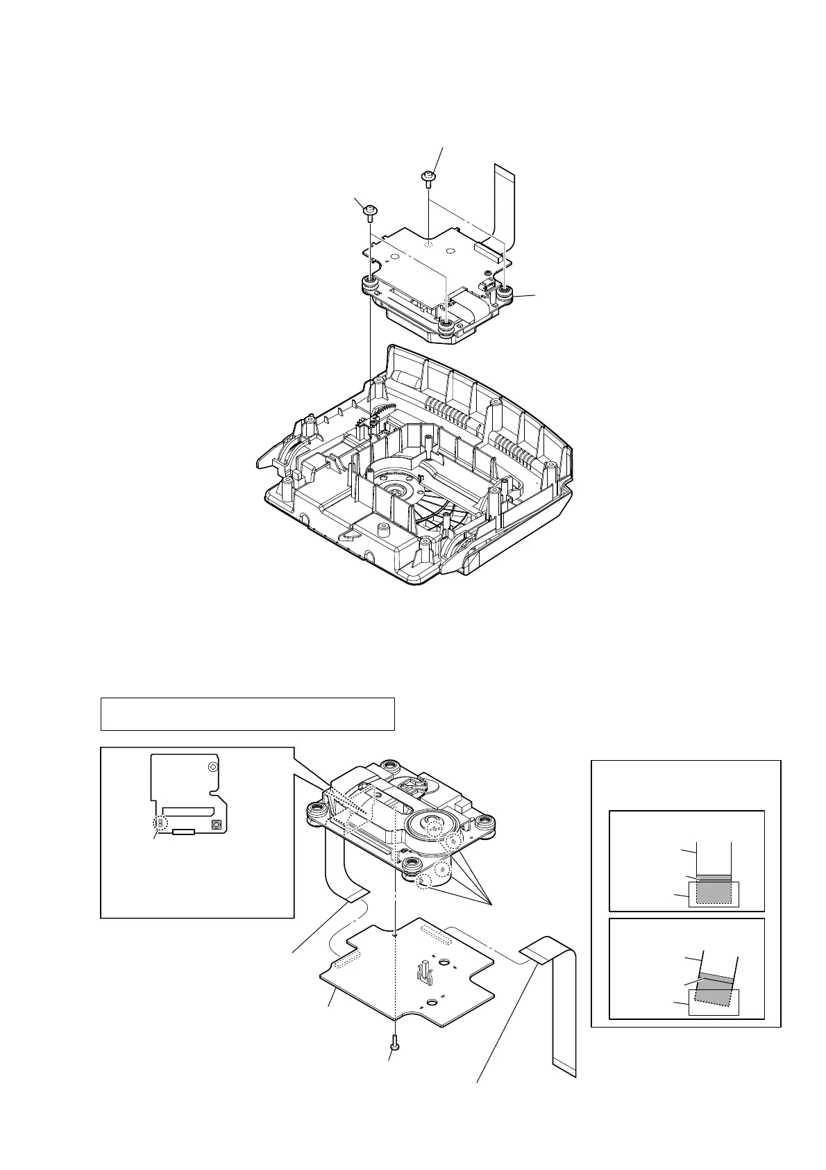
2-6. CD BLOCK ASSY
2-7. CD BOARD
1 two tapping screw
(PWH B2.6)
1 two tapping screw
(PWH B2.6)
2 CD block assy
– Cabinet (upper) block bottom view –
2
Solder the short-land.
4 Remove four solders.
1 flexible flat cable (27 core)
(CN702)
3 flexible flat cable (16 core)
(CN701)
5 tapping screw
(P B2.6)
6 CD board
colored line
colored line
Insert is straight to the interior.
Insert is incline
flexible flat
cable
flexible flat
cable
connector
connector
OK
NG
Note 1:
Before disconnecting the flexible flat cable (16 core)
of optical pick-up block, solder the short-land.
Note 2: When assembling the CD board,
remove the solder of short-land
after connecting the flexible flat
cable (16 core).
Note 3:
When installing the flexible flat
cable, ensure the colored line.
No slanting after insertion.
 Loading...