ZS-RS70BT/RS70BTB
ZS-RS70BT/RS70BTB
2525
SECTION 4
ELECTRICAL CHECKS
TUNER SECTION
0 dB = 1 V
[AM] (RS70BT only)
Setting:
Function: RADIO
Band: AM
AM RF signal
generator
30% amplitude
modulation by
400 Hz signal
Output level:
as low as possible
Put the lead-wire
antenna close to
the unit.
JACK board
i jack (J301)
unit
+
í
level meter
32 :
[FM]
Setting:
Function: RADIO
Band: FM
FM RF signal
generator
75 kHz frequency
deviation by
1 kHz signal
Output level:
as low as possible
JACK board
i jack (J301)
unit
0.01PF
+
í
level meter
TUNER board (RS70BT):
FM test point (Not print) (GND)
DAB board (RS70BTB):
FM test point 2 (Not print) (GND)
32 :
TUNER board (RS70BT):
TP1
DAB board (RS70BTB):
FM test point 1(Not print)
Note: Perform FM frequency coverage check after removing FM tele-
scopic antenna (ANT1).
no mark: E41 model
( ): E92 and MX models
AM FREQUENCY COVERAGE CHECK
Check that reading on level meter is the maximum
Confi rmation 531 (530) kHz
Confi rmation 1,602 (1,710) kHz
FM FREQUENCY COVERAGE CHECK
Check that reading on level meter is the maximum
Confi rmation 87.5 MHz
Confi rmation 108 MHz
• Abbreviation
E41 : Bolivian, Chilean, Paraguayan, Peruvian and
Uruguayan models
E92 : Venezuelan, Panamanian, Honduran, Guatemalan,
Colombian, Costa Ri-ca, Dominican, Ecuadorean and
El Salvador models
MX : Mexican model
CD SECTION
Note:
1. CD block is basically constructed to operate without adjustment.
2. Use YEDS-18 disc (Part No. 3-702-101-01) unless otherwise indicat-
ed.
3. Use an oscilloscope with more than 10 M impedance.
4. Clean the object lens by an applicator with neutral detergent when the
signal level is low than specifi ed value with the following checks.
5. Check the focus bias check when optical pick-up block is replaced.
FOCUS BIAS CHECK
+
–
CD board
TP (RFOUT)
TP (VC)
oscilloscope
Procedure:
1. Connect the oscilloscope to RFOUT and VC on the CD board.
2. In the standby state, press the [POWER] (Except AEP and UK
models)/[OPERATE] (AEP and UK models) button to turn the
power on.
3. Press the [CD] button to turn the CD function.
4. Set the disc (YEDS-18) and press the [MANUAL PRESET
u
] button to playback.
5. Confi rm that oscilloscope waveform is as shown in the fi gure
below. (eye pattern)
A good eye pattern means that the diamond shape () in the
center of the waveform can be clearly distinguished.
VOLT/DIV: 200 m
TIME/DIV: 500 ns
level: 1.0 ± 0.5 Vp-p
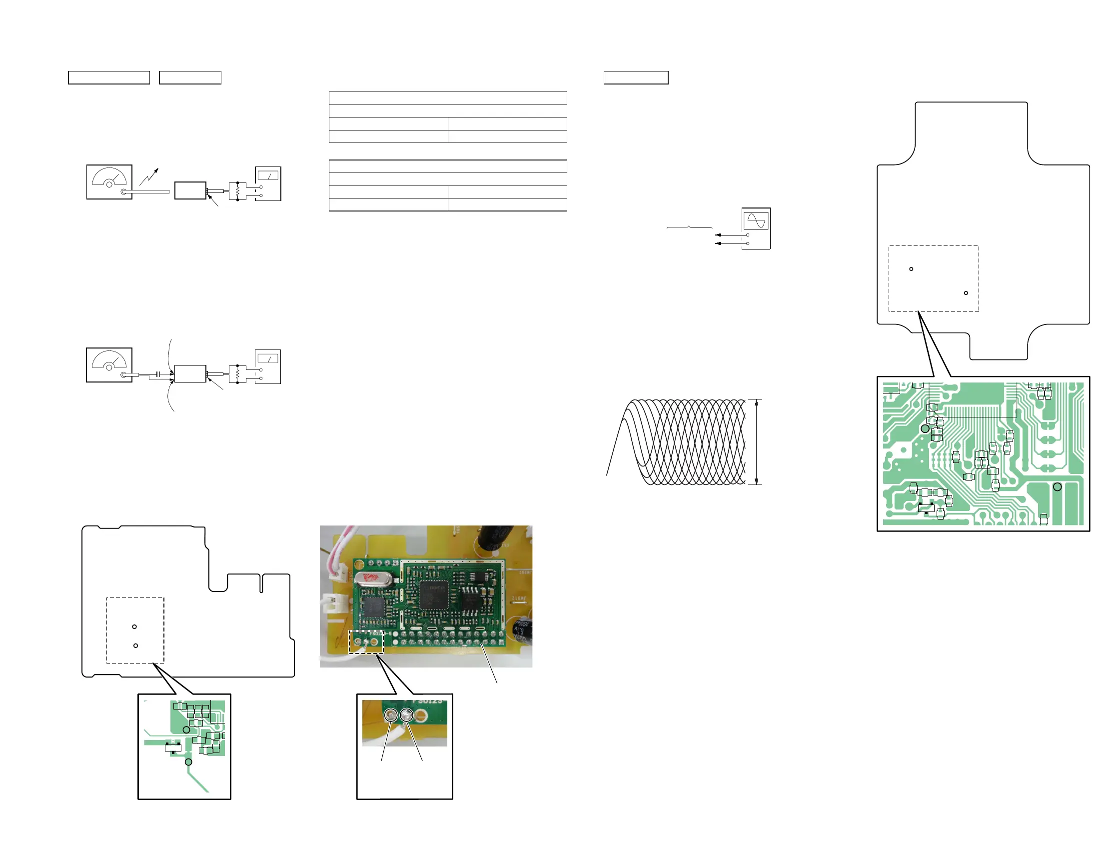
Connection Location:
TP
(VC)
TP
(RFOUT)
– CD Board (Conductor Side) –
R728
C719
C721R732
C759
R701
C702
120
80 21
C754
C703
C709
C710
C708
C701
C704
C715
C712
C714
C711
R724
C716
R719
R717
R721
R723 R533
ECB
Q701
R534
TP
(VC)
TP
(RFOUT)
Connection Location:
TP1
FM test point
(GND)
– DAB Board (Component Side) (RS70BTB) –
– TUNER Board (Conductor Side) (RS70BT) –
TP1
C5
C2
C1
C6
1
R13
R1
R2
L1
C10
D3
FM
test point
(GND)
FM
test point 2
(GND)
FM
test point 1
DAB module
 Loading...