Registered Quality System to ISO 9001:2008
41/60
Form 912
sorinc.com
913-888-2630
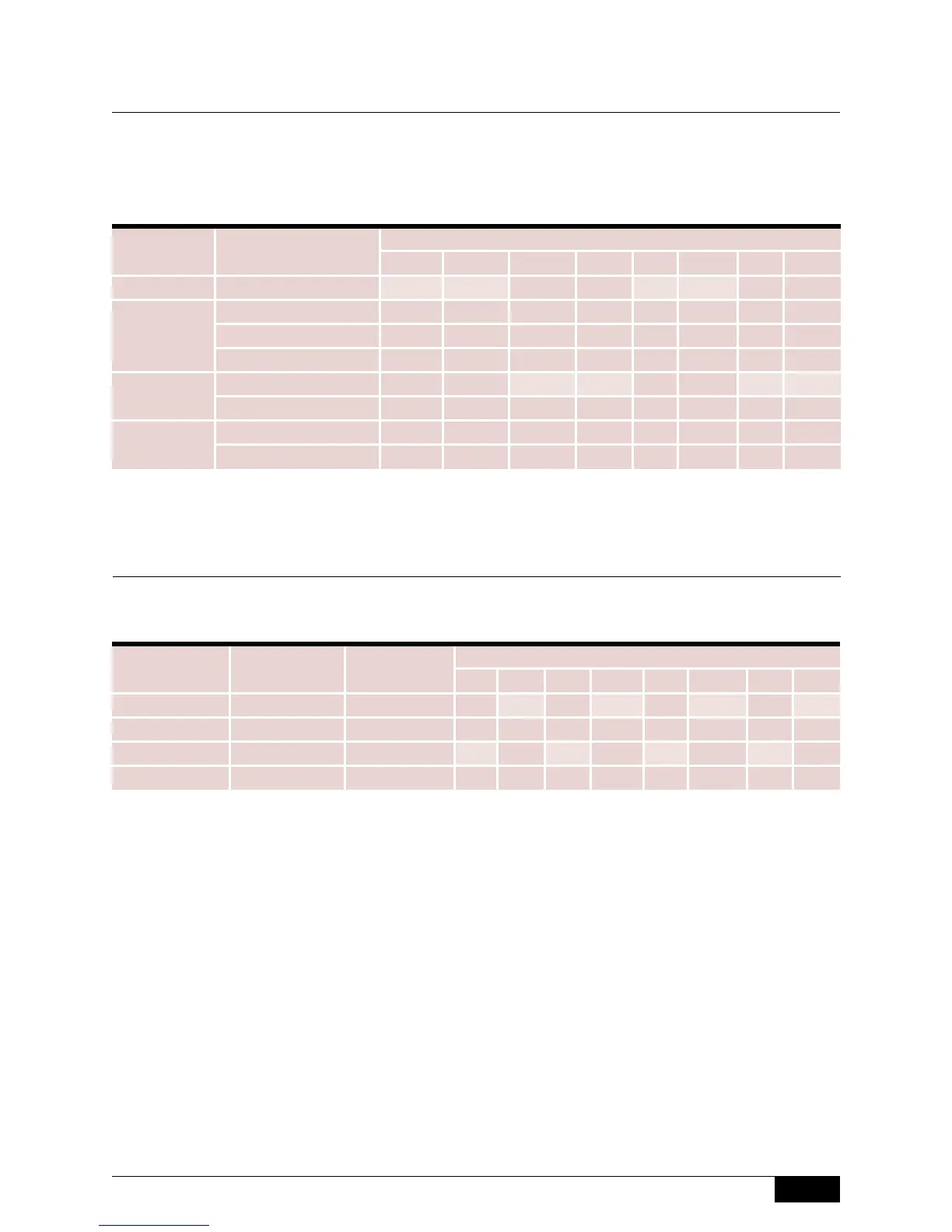
Select a process connection style, size and rating from the chart below. Consult the factory for
variations. Flanged process connections may reduce the maximum working pressure of the unit.
Step 3: Process Connection
751A -F7A-B-A3-N1-CRTT
Step 4: Trim Material
Select the internal trim material from the chart below.
751 A -F7A-B-A3-N1-CRTT
Standard displacer spring material is Inconel 600.
750 Series
Size Style
Model
750 751 752 753 754 755 756 757
2-1/2” NPT F7A F7A - - F7A F7A - -
3”
NPT F3A F3A - - F3A F3A - -
150# RF Flange - - F3C F3C - - F3C F3C
300# RF Flange - - F3D F3D - - F3D F3D
4”
150# RF Flange - - F4C F4C - - F4C F4C
300# RF Flange - - F4D F4D - - F4D F4D
6”
150# RF Flange - - F6C F6C - - F6C F6C
300# RF Flange - - F6D F6D - - F6D F6D
Displacer
Material
Attraction
Sleeve
Construction
Material
Model
750 751 752 753 754 755 756 757
316/316L SS 400SS A only - B - B - B - B
316/316L SS 316/316L SS A or C - C - C - C - C
Porcelain 400SS A only P - P - P - P -
Porcelain 316/316L SS A or C R - R - R - R -
 Loading...