Version: 1
Revision Date: 02/2018
N
2-BLAST
®
FPS-500
O&M Manual
Page: 13 of 25
Contact us Toll-Free: (888) 526-6284
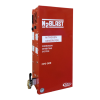
5.2 INSTALLATION ARRANGEMENT
See below for basic setup. Refer to the general arrangement drawing for detail
instructions included with the installation package.
Z
Figure 3: Nitrogen Generator Wall Mount Installation Setup
Optional air compressor,
new or pre-existing
Should this handle be in
the closed position, the
generator will be bypassed
by air. This will light a red
indicator and trigger an
alarm if connected.
Note: Generator is on line,
and functioning, during
this state.
Note: All N2-BLAST
®
models are factory
equipped with ½” NPT
Female connections.
Air maintenance device
recommended
Only one line
in/out when
using bypass
Nitrogen tank
provided with
brackets and
strap
Note: Nitrogen generator dimensions: 12.75” W x 12” D x 27” H (Cabinet dimensions)
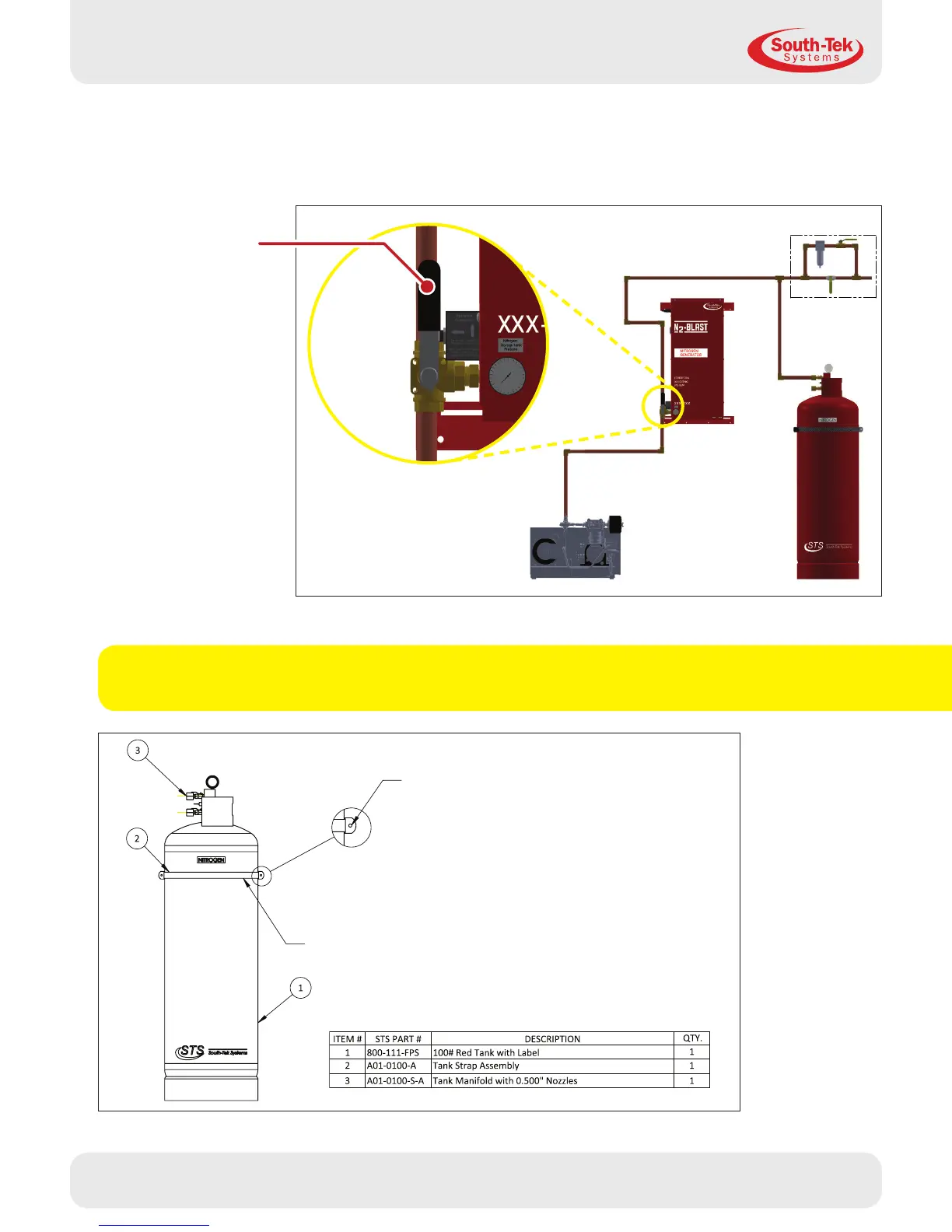
Nitrogen tank dimensions: 15” Diameter x 50” H (Recommend 55” for manifold clearance)
Figure 4: FPS nitrogen tank details and connections
D-Ring assembly
should be secured to
wall using ¼” hardware
(not supplied)
Wrap strap around tank
and use plastic clip to
secure tank to wall
Detail A
 Loading...