22
Route each wire from the sensors neatly down the wind-screen pillars and under the
dashboard
.
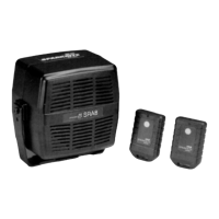
Ultrasonic Control Unit
IMPORTANT
The ultrasonic detector must only be connected to the alarm after removal of the fuse
from the red 12V supply wire. Reconne ct the fuse once the detector h as been
installed.
Select a suitable m ou nting position for the control unit under the dashboard in the
driver or passenger compartment. Route the wires from the ultrasonic sensors and
plug-in to the correct sockets (marked T and R).
Do not mount the control unit until the installation is complete. Secure in place with
either the velcro or screws/washers supplied.
Feed the 3 wa y cable and plug from the ultrasonic co ntrol unit, through an existing
rubber grommet in the bu lkhead, to the alarm location under the bonnet. Connect the
ULTRASONIC DETECTOR UNIT plug direct into the 3 way sensor socket on the m ain
alarm unit.
Ultrasonic Sensitivity Adjustment
The adjuster which control the sensitivity is located on the top of the main ultrasonic
unit. Turning the adjuster ANTI-CLOCKWISE decreases the ultrasonic sensitivity,
turning the adjuster CLOCKWISE increases the sensitivity.
• Turn the adjuster to a middle position.
• Sit in the rear of the vehicle with all doors and windows closed. Position the
ultrasonic control unit where the RED (Sensitivity) LED can be seen.
• Arm the alarm with remote control transmitter.
NOTE: The alarm will not trigger until the exit delay has expired.
• Adjust the sensitivity of the u ltrasonics so that movement in the rear of the