9 Related Documents
9.1 General assembly drawings
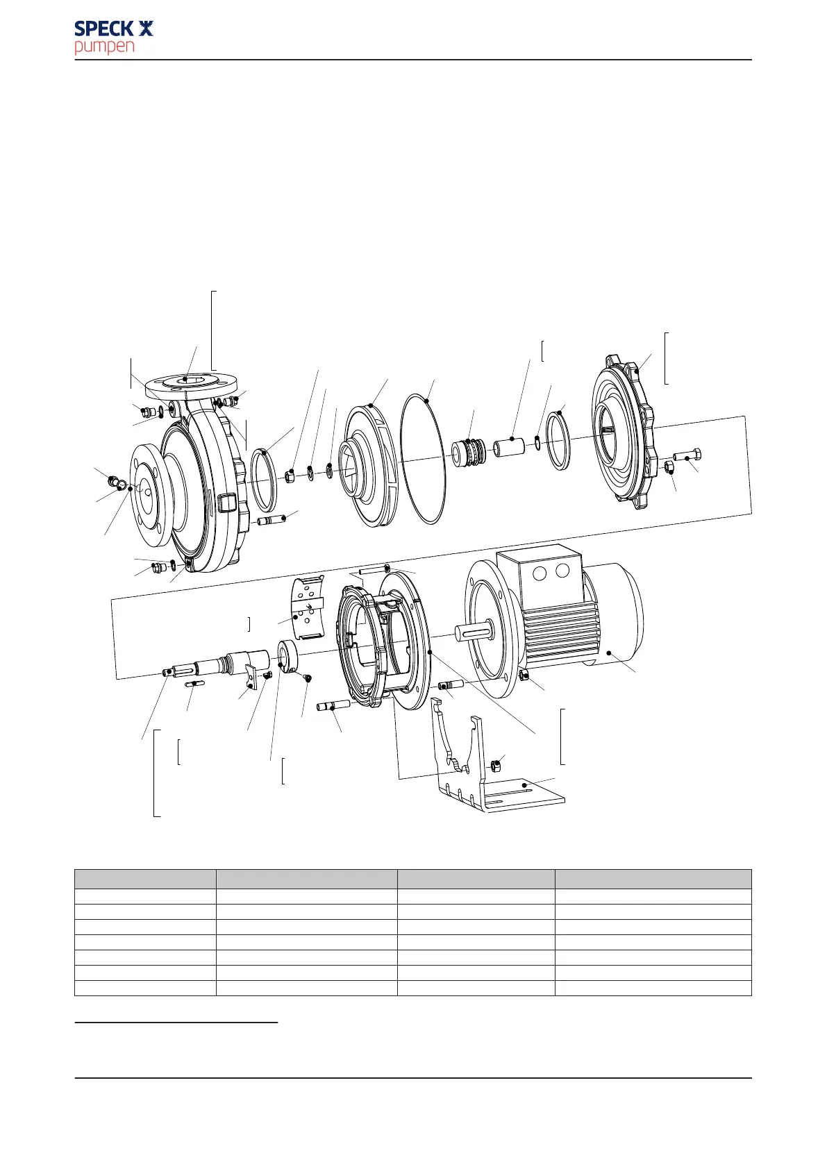
9.1.1 Variant with single mechanical seal and bolted casing cover
Table 20: This view applies to the following pump sizes:
32-200
32-250
40-200
40-250
40-315
50-200
50-250
50-315
65-200
65-250
65-315
80-250
80-315
80-400
100-250
100-315
100-400
125-250
125-315
125-400
150-250
150-315
150-400
[ Supplied in packaging units only
902.11
DA
AE
903.03
411.03
1M
903.04
411.04
903.01
411.01
E
102
102
411.01/.02/.03/.04
502.01
902.01
903.01/.02/.03/.04
920.01
903.02
411.02
DA
AE
502.01
902.01
920.95
930.95
550.95
230 400.10
433
502.02
400.75
523
523
400.75
161
161
502.02
902.15/.51
920.15
920.01
901.30
801
920.11
341
341
68-3.01/.02
901.31
902.11
920.11
920.15
183
901.31
210
940.01
931.95
901.50
914.24
902.15
902.51
515
515
914.24
210
515
515
914.24
550.95
920.95
930.95
940.01
68-3.01/.02 68-3
Fig. 11: Variant with single mechanical seal and bolted casing cover
Table 21: List of components
7)
Part No. Description Part No. Description
102 Volute casing 68-3.01/.02 Cover plate
146 Intermediate lantern 801 Flanged motor
161 Casing cover 901.30/.31/.50 Hexagon head bolt
183 Support foot 902.01/.06/.11/.15/.50/.51 Stud
210 Shaft 903.01/.02/.03/.04/.08 Screw plug
230 Impeller 914.24 Hexagon socket head cap screw
341 Drive lantern 920.01/.06/.11/.15/.95 Hexagon nut
7)
Some individual components might not be applicable, depending on the size and material.
9 Related Documents
Normblock
49 of 58