SPHINX Project Eight Service Manual
2
1. UNPACKING .......................................................................................................................................3
2. SPHINX WARRANTY CARD ..............................................................................................................3
3. CONTACTING THE MANUFACTURER.............................................................................................3
4. TECHNICAL SPECIFICATIONS.........................................................................................................4
5. GENERAL CHECKLIST......................................................................................................................5
Serial number and software version ............................................................................................................ 5
Input functions .............................................................................................................................................5
Channel imbalance...................................................................................................................................... 5
Remote Control............................................................................................................................................5
6. SPHINX REMOTE CONTROL............................................................................................................6
Buttons and LED indication .........................................................................................................................6
Operation.....................................................................................................................................................7
Selecting without switching..........................................................................................................................7
'Learning' the commands.............................................................................................................................7
Changing a command..................................................................................................................................7
Erasing all commands of one component.................................................................................................... 7
The LED during Normal mode ..................................................................................................................... 8
The LED during 'Learn' mode ......................................................................................................................8
Batteries.......................................................................................................................................................8
Other things worth knowing... ......................................................................................................................8
Encountering problems................................................................................................................................ 8
7. MEASUREMENTS ..............................................................................................................................9
General set-up.............................................................................................................................................9
Necessary Equipment..................................................................................................................................9
Audio signal distortion measurement........................................................................................................... 9
Set-up ..........................................................................................................................................................9
8. OUTPUT DC-OFFSET ADJUSTMENT.............................................................................................10
Set-up ........................................................................................................................................................10
Adjustment................................................................................................................................................. 10
9. PROBLEMS AND SOLUTIONS........................................................................................................11
10. DIAGRAMS AND PARTS LISTS ....................................................................................................12
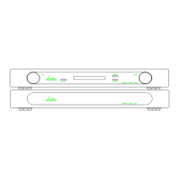
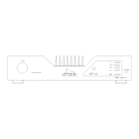
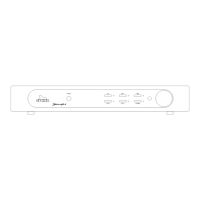
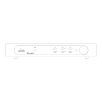
Figure 1: Front panel .................................................................................................................................12
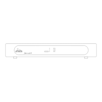
Figure 2: Rear panel..................................................................................................................................12
Index of diagrams and drawings................................................................................................................13
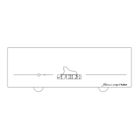
Figure 3: Connection Diagram for testing the Project Eight.......................................................................14
Figure 4: Display Board Schematic Layout................................................................................................15
Figure 5: Construction Drawing for top cover plate.................................................................................... 16
Figure 6: Schematic Operational Diagram Project Eight ...........................................................................17
Figure 7: Schematic Overview of all relevant potentiometers.................................................................... 18
Figure 8: Disamp-96 ..................................................................................................................................19
Figure 9: Functional Schematic .................................................................................................................20
Figure 10: Left Power Supply..................................................................................................................... 21
Figure 11: Right Power Supply ..................................................................................................................22
Figure 12: Input/Output..............................................................................................................................23
Figure 13: Left Volume Control..................................................................................................................24
Figure 14: Right Volume Control................................................................................................................25
Figure 15: Left Output Amp........................................................................................................................26
Figure 16: Right Output Amp .....................................................................................................................27
Figure 17: Left Input Amp ..........................................................................................................................28
Figure 18: Right Input Amp........................................................................................................................29
Figure 19: Power Supply Unit ....................................................................................................................30
Figure 20: PCB drawings...........................................................................................................................31
Parts List.................................................................................................................................................... 32