20
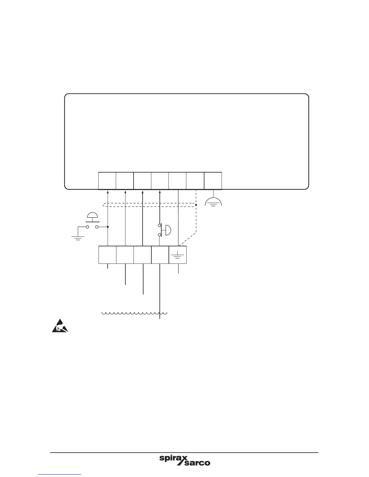
5.5 Optional external test switch wiring diagram
If an external test switch is required, it is possible to wire in a panel mounted switch as shown
in Figure 11. For high alarm a Normally Open (NO) switch is used to connect the tip to the
probe body. For low alarm a Normally Closed (NC) switch is used to disconnect the probe tip
from the controller. In order to prevent continuous alarms a spring-loaded, or a key operated
switch is recommended.
Signal circuit
(View from the top)
50
Alarm
1
High alarm
test switch
(normally
open)
51
52 53
54
55 56
Pump
tip
HI
Pump
tip
LO
Alarm
2
Com Screen E
Connect to a clean local
earth in the panel
*Low alarm test switch
(Normally Closed)
LP10-4
High
alarm
Pump
off
Pump
on
Low
alarm
Note:
Do not connect terminal 55 to any other earth.
Ensure resistance from the probe body to the pipework/boiler shell is less 1 ohm.
E = Functional earth. Connect these pins to earth local to the panel.
Fig. 11 Signal circuit LP10-4 - Pumping-in with one high and one low alarm
Front
*
Back