Installing U1 OTA Modules on the Landslide E10
Before You Begin
Spirent Landslide Test System Installation Guide | 41
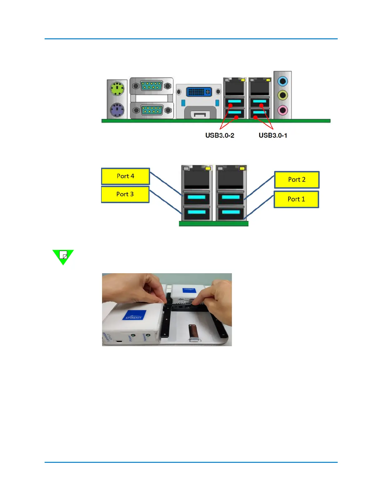
Figure 4-8. Rear I/O Panel of the E10
Figure 4-9. USB Port Numbering
Note: Landslide software configuration of the OTA modules is determined by rear panel
USB port, U1 OTA 1/Port1, OTA2/Port 2, etc.
Figure 4-10. Long USB Cable Placement - step 1
Route the long USB cables using cable
ties in between modules.
Loop the long USB cables above the
antennas to prevent accidental pulling.