36
S1
S2
S2
S6
S6
S6
S6
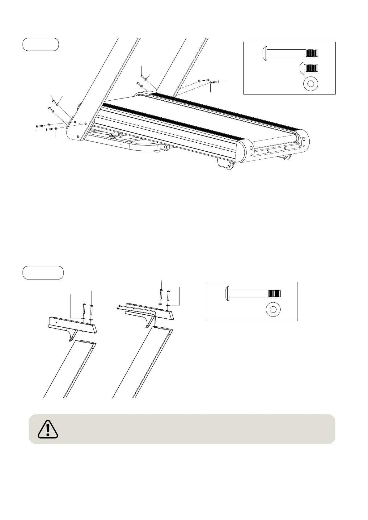
• Align the left and right support tubes so that you can mount the screws S1.
• Screw the four screws S1 (Allen key M8×60) together with the four washers S6 into the support tube.
Do not tighten the screws yet.
• Screw the four screws S2 (Allen key M8×16) with the four washers S6 into the support tube. Do not
tighten the bolts yet.
Do not tighten the screw connections until step 4 has been completed.
• Pull the device control cable from the base
through the right bracket tube.
• Pull the control cord through the right
console bracket C.
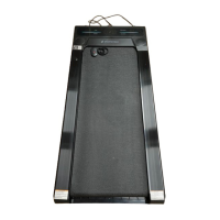
STEP 2
• Place the right bracket holder C on the support tube. Mount the two screws S8 (Allen
M8×70) with their washers.
• Mount the left bracket holder using the screws S8 (Allen M8×70) and washers S6.
STEP 1
4 x S1
4 x S2
8 x S6
(C)
(C)
S8
S6
S6
4 x S8
S64 x
Note: Ensure that the connection cable is not subjected to tensile stress or twisted in the
holder tube.