33
TG 2-25 @ TG 23-65
13 2
TG 58-80 @ TG 360-150
3 1 2
B
A
C
A
B
C
suck-back grooves
A.0500.451 – IM-TGGP/07.02 EN (03/2016)
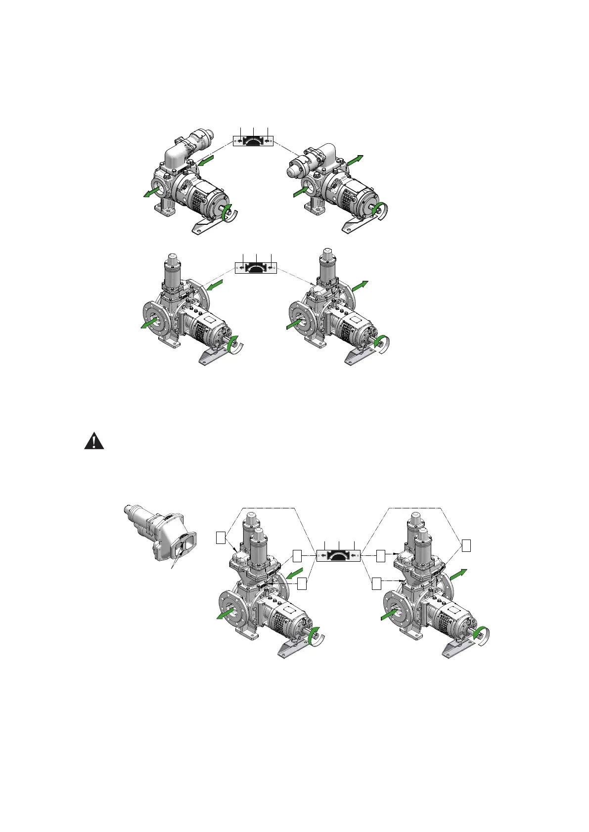
3.19.5 Shaft rotation for pump with safety relief valve
The shaft rotation determines which port of the pump is suction and which is discharge.
The relation between the shaft rotation and the suction/discharge side is indicated by the rotation
arrow plate attached at the valve casing of the safety relief valve.
Note! Shaft rotation is always viewed from the shaft end towards the pump.
Unless otherwise specified on the order, TopGear pumps are built at the factory for clockwise
rotation (left figures above), which we define as the standard direction of rotation.
The small arrows 2 and 3 indicate the flow direction of the pumped liquid.
Always make sure that shaft rotation corresponds with the position of the discharge and suction
ports and the direction indicated by the rotation arrow plate.
If the shaft rotation is correct in relation to the port position but different from the direction indicated
by rotation arrow plate, the safety relief valve must be disassembled and turned around by 180°.
If the pump rotates in both directions, a double safety relief valve is required.
When a double safety relief valve is installed three arrow plates are attached – one on each valve
(A and B) indicating the liquid flow direction of each valve (small arrows 2 and 3) and one on the
Y-casing (C) indicating the most favourable direction of rotation of the pump (arrow 1).
The two suck-back grooves will help to evacuate air or gases during start-up or whilst running. As
they only function in one direction of rotation, the Y-casing should be positioned in such a way that
the suck-back grooves are placed towards the most used suction side.
In case of doubt, contact your local distributor.
Be sure that the safety relief valves are mounted opposite each other so that the arrow plates on the
safety relief valves (A and B) are indicating opposite liquid flow directions.
 Loading...