56
7310
7050 7320 7330 7150
7040
7010 7110
7300
H
A.0500.451 – IM-TGGP/07.02 EN (03/2016)
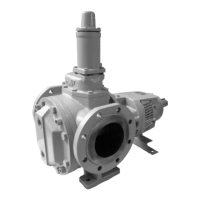
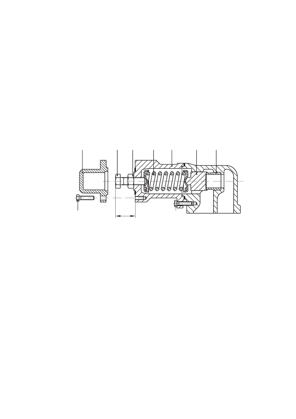
4.6 Relief valve
• The relief valve may not be disassembled before the spring has been released completely
• Before releasing the spring, measure the position of the adjusting bolt, so that the
spring afterwards can be adjusted to its original opening pressure
4.6.1 Disassembly
• Undo the screws (7310) and the cover (7050).
• Measure and record the exact position of the adjusting bolt (7320). (See dimension H).
• Loosen nut (7330) and adjusting screw (7320) until the spring (7150) has been completely
released.
• Remove spring casing (7040) by loosening the screws (7300).
• Spring (7150), valve (7010) and valve seat (7110) are now accessible.
4.6.2 Assembly
• Check the sealing face of both valve seat (7110) and valve (7010).
• In case of a slightly damaged surface, this can be rubbed with an appropriate emery paste. In
case of severe damage however, valve seat (pay attention to shrink fit) and valve must be
replaced.
• Always mount a correct type of spring with the original dimensions and an appropriate
adjusting screw (see section 3.18.3).
• Fit spring casing (7040) and bolts (7300).
• Fit adjusting screw (7320) and nut (7330), screwing the adjusting screw to measured
distance H.
• Fix this position by tightening the nut (7330).
Remark: When another type of spring and/or adjusting bolt is mounted, the opening pressure
of the relief valve must be adjusted hydraulically.
• Fit cover (7050) and screws (7310).
Assembly and disassembly of the safety relief valve
 Loading...