Home
SSANGYONG
Automobile
Rexton Y290 2012
SSANGYONG Rexton Y290 2012 User Manual
5
of 1
of 1 rating
682 pages
Give review
Manual
Specs
To Next Page
To Next Page
To Previous Page
To Previous Page
Loading...
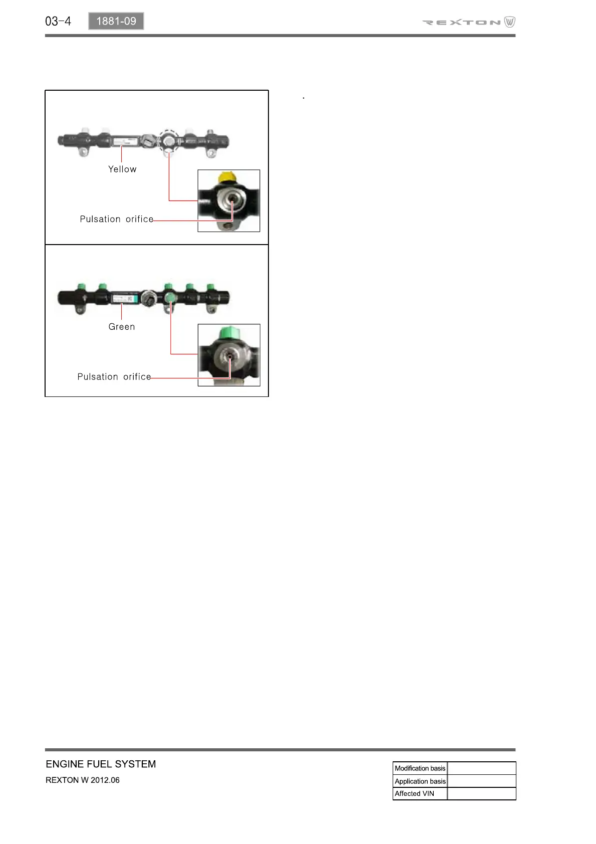
2) Common Rail
The
orifice
is
added
to
the
connection
to
the
fuel
p
ipe
of
the
HP
pump
to
prevent
the
fuel
pulsation
by
the
fuel
supply
and
fuel
cut
according
to
the
increase
of
injected
fuel
vo
lume.
(It
is
also
installed
on
the
connection
of
the
high
pressure
fuel
supply
line
of
the
HP
pump.)
D27DTP & D27DT (EU IV)
D27DT
19
21
Table of Contents
Fuel System
3
Lubrication System
5
Intake System
7
Exhaust System
8
Specifications
13
Engine Performance Curve
14
Common Rail
20
Intake System Layout
24
System Description
43
Operation
47
Setting a Desired Speed
47
Component Locator
53
Side View
55
Description and Operation
56
Cleanliness and Care
56
On-Engine Service
56
Performance Curve
58
Special Tools and Equipment
59
Fastener Tightening Specifications
62
Fuel System Specification
64
Oil Circulation
69
General Specifications
71
Special Tools and Equipment
72
General Description
74
Charging System Operation
79
Charging Time Required
79
Ignition System Operation
80
Electronic Ignition System Ignition Coil
80
Engine Data Display Table
82
System Description
84
Operation
88
Major Changes
96
Specifications
97
Electrical Performance
97
Rated Load
98
Input Signals
99
Operation
104
Function Description
104
Ignition Key Reminder
128
Time Lag Power Window Control
154
Theft Deterrent
157
Circuit Diagram
168
Operating Condition
174
Transmitter Coding
174
Diagnostic Connector
175
Major Changes
179
System Diagram
182
Circuit Diagram
187
Specifications
190
Outside Rearview Mirror
191
Major Changes
194
Switch Operation
195
Easy Access Function
200
Circuit Diagram
204
Specifications
207
System Layout
209
Warning Lamps and Indicators
210
Display Sequence
221
System Analysis
223
ESP Warning Lamp
229
Self-Diagnosis
234
Variant Coding
234
Multi-Function Switch
235
Major Changes
236
Exterior Lamps
245
Auto Light
250
License Plate Lamp
251
Front Fog Lamp
254
Turn Signal Lamp
255
Back-Up Lamp
257
Interior Lamps
259
Front Room Lamp
261
Glove Box Lamp
263
Sun Visor
263
Wiper Control
265
Major Changes
266
Wiper and Washer System
267
Rear Wiper Switch
280
System Layout and Overview
291
Auto Light Control
295
Operation Mode of Rain Sensing Wiper System
298
Specification
299
Major Changes
300
Operating Process
304
Detection Range
304
Operation Mode
309
Circuit Diagram
311
Flow Chart
312
Specification
314
Major Changes
316
Specifications
320
Operating Process
324
Digital Clock
326
General Information
327
Features and Specifications
329
Shift Pattern Diagram
332
Tightening Torque
333
Cooling System
336
Mode Descriptions
337
Kickdown Function
338
Limp Home Mode
339
Electronic Control System
340
Can Network
344
Network Communication
344
Power Flow
345
Specifications
371
Tightening Torque
373
Major Changes
374
Power Flow
377
Circuit Diagram
385
Specification
387
Special Service Tools
388
Tightening Torque
390
Gear Ratio
399
Power Flow
400
Shifting Mechanism
404
General Specifications
405
System Components
407
Sectional View
408
Front View and Rear View
414
Power Flows
416
Interlock System
419
Backup Lamp Switch
421
Circuit Diagram (Backup Lamp)
427
Exploded View
434
Power Flow
435
4WD Operation Overview
441
Mode Selection
443
Circuit Diagram
447
System Layout
452
Specification
459
Tightening Torque
459
Wheel Alignment
461
Layout and Components
462
Troubleshooting
468
Specification
477
Air Bleeding
482
System Layout
496
Sectional Diagram
498
Hydraulic Circuit
500
System Overview
503
Components and Layout
505
ABS Warning Lamp
508
System Operation
509
Hydraulic Circuit Diagram
515
Specification
519
Terms and Acronyms
521
Operation of Components
522
Operation
540
Operating Description
546
Circuit Diagram
551
Specifications
553
Special Service Tools
555
Inspection and Maintenance
558
System Layout
565
Steering Cylinder
565
Specifications
567
Operating Process
571
System Control
574
Circuit Diagram
576
Wheel Module
577
Block Diagram
584
Tire Pressure Display
589
Tire Inflation Procedure
591
Specifications
594
Trouble Diagnosis
595
Appearance Check
596
Wheel Balance
607
Specifications
611
Ventilation System
618
Basic Operating Principle
620
Warnings for Airbag
625
Major Replacement Parts after Air Bag Deployment
626
Operating Conditions
630
Front Airbag System
630
Side Airbag System
631
Operation Process
632
Air Bag System Block Diagram
632
Air Bag Deployment Signal Output (Crash Out)
635
Air Bag Warning Lamp Operational Conditions
637
Circuit Diagram
638
Major Changes
640
Front Seat Assembly
640
Position Memory Setting
647
Operating Conditions
647
Circuit Diagram
654
Cautions for Operation
661
Major Changes
662
Sunroof Switch
662
Operating Process
664
Emergency Operation
667
Radiator Grille
672
Front Bumper
672
Tailgate Glass
676
Rear Spoiler
676
Rear Bumper
677
Jack Points
681
5
Based on 1 rating
Ask a question
Give review
Questions and Answers:
Need help?
Do you have a question about the SSANGYONG Rexton Y290 2012 and is the answer not in the manual?
Ask a question
SSANGYONG Rexton Y290 2012 Specifications
General
Brand
SSANGYONG
Model
Rexton Y290 2012
Category
Automobile
Language
English
Related product manuals
SSANGYONG REXTON
242 pages
SSANGYONG Rexton 2008
156 pages
SSANGYONG Rexton 2010
101 pages
SSANGYONG REXTON 2006.09
806 pages
SSANGYONG REXTON 2007.09
768 pages
SSANGYONG Rodius 2012.07
715 pages
SSANGYONG Rodius 2013.02
796 pages
SSANGYONG MUSSO
182 pages
SSANGYONG STAVIC
297 pages
SSANGYONG ACTYON
321 pages
SSANGYONG Actyon 2008
81 pages
Actyon Sports II 2012.01
719 pages
 Loading...