SST-PFB-SLC User’s Guide
24
Connect to the serial port using any communication software such as
Windows Terminal or Hyperterminal. The scanner serial port supports any
baud rate from 9600 baud to 115 kbaud, with no parity, 8 data bits, 1 stop bit.
The scanner automatically detects the baud rate you are using by adjusting the
baud rate until it receives an “*”.
4.3 Status LEDs
4.3.1 SYS LED
If you are using the scanner as a DP master and a DP slave, the SYS LED
shows the status of both operations sequentially. The master status is flashed
first, followed by the slave status. If you are using the scanner for FDL the
sequence is DP Master DP slave FDL messages and FDL SAPs.
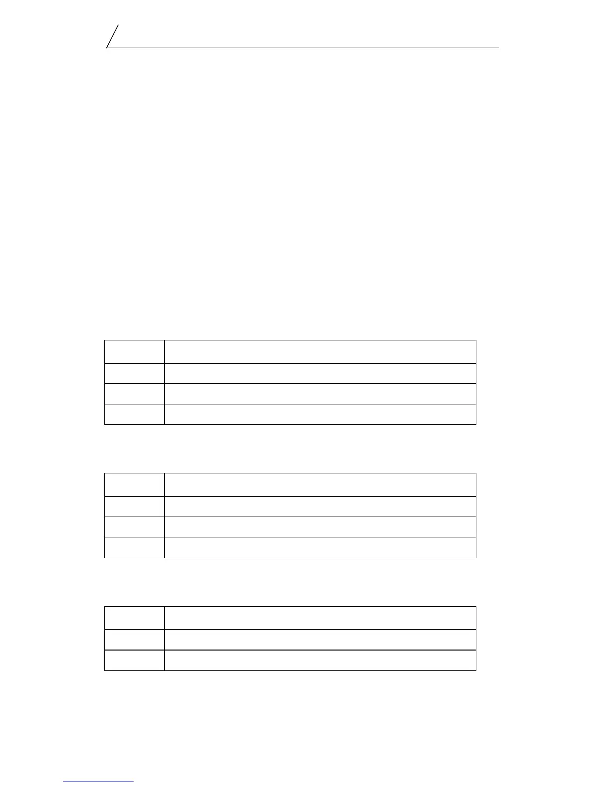
The following table provides a description of the LEDs:
DP Master.
DP Slave
FDL
At system start up, the SYS LED flashes green for two seconds.
Color Indication
Red one or more slaves is reporting a fault condition
Amber the module is in program or test mode
Green the module is scanning in Run mode.
Color Indication
Red the slave is not being scanned or is faulted
Amber the slave is being scanned in program mode
Green the slave is being scanned in run mode
Color Indication
Red a fault has occurred
Green the system is functioning normally