SST-PFB-SLC User’s Guide
44
5.6 Using the Watch-Dog Timer
Under “brown-out” power conditions the AB SLC Processor can enter a reset
condition, while the SST-PFB-SLC module remains fully functional.
Although all installations of the SLC Scanner products should have adequate
power conditioning and power failure equipment, these “brown-out”
conditions can still occur. To ensure that the SST-PFB-SLC returns the
fieldbus to a known, safe state, a watch-dog timer has ben implemented in the
firmware.
5.6.1 How the Host Watch Dog works
After the SST-PFB-SLC has been reset or powered up, a default time of 100
ms is used for the watchdog period, which exists for communications with the
SLC Processor. If the SST-PFB-SLC does not get an update of I/O from the
SLC processor with the 100 ms period, the scanner faults.
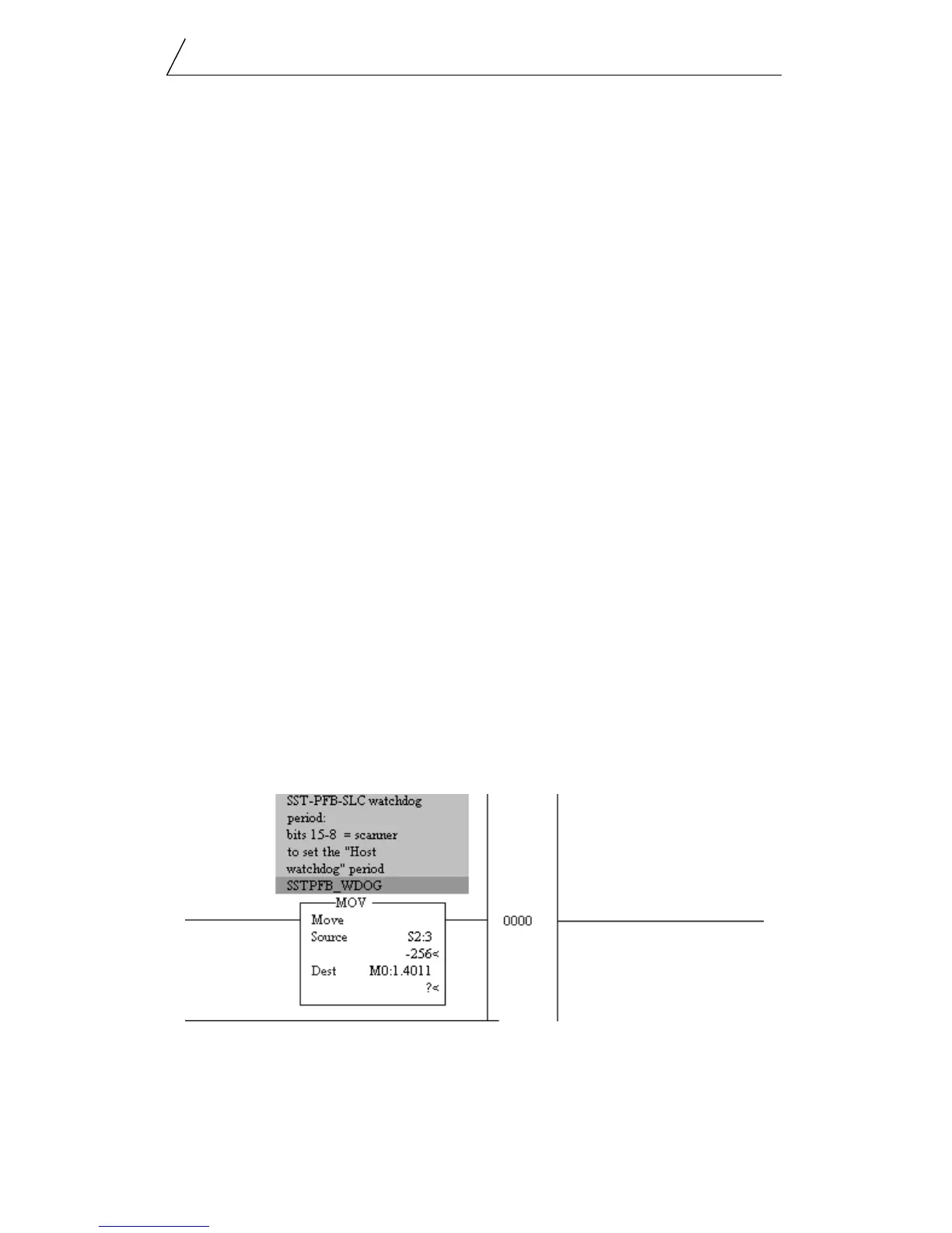
The period of the watchdog timer may be set to a different value by writing
the contents of the S:3 work (from the SLC Processor’s status file) to the
M:0[slot].4011 register. The firmware takes the upper 8 bits of the S:3 word
(the user maximum scan time setting) and applies it as the new watchdog
period. in this way, the user’s program can control the watchdog time for the
SST-PFB-SLC scanner and avoid any false faults that result from an extended
SLC processor scan time.
Logic Example
The following rung of logic can be used in the your program to automatically
have the SST-PFB-SLC scanner’s watchdog period track that of the SLC
processor.
The SST-PFB-SLC is located in the first slot of the SLC rack. The watchdog
register is M0:1.4011.
 Loading...