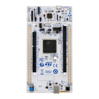
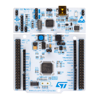
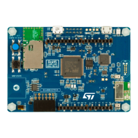
The green LED LD5 is lit when the B-L4S5I-IOT01A Discovery kit for the IoT node is powered by the 5 V correctly.
The power tree is shown in Figure 12. Power tree.
Figure 12. Power tree
USB_ST_LINK
USB_OTG_FS
ARDUINO
®
STM32F103 ST_LINK
Bi-color LED
ST_LINK debug
TAG
MCU STM32L4S5VIT6
64-Mbit QSPI Flash
(MX25R6435F)
MP34DT01 digital microphone
ISM43362-M3G-L44
Wi-Fi
®
module
SPBTLE-RF
Bluetooth
®
module
SPSGRF Sub-GHz
(Spirit) module
not fitted
ST25DV04K NFC module
LIS3MDL
3-axis magnetometer
LSM6DSL
3D gyroscope
LPS22HB
Digital barometer
HTS221
Humidity and temperature
VL53L0X
ToF and gesture detection
STSAFE-A110
Authentication and security
MP34DT01 digital microphone
LDO
LD1117S33TR
3V3
5V
VDD_MCU
JP5
IC14
JP4
3V3_Wifi
LDO
LT1963EST-3.3
5V
IC12
Pmod™
Power switch 5V/1.2A
ST890CDR
IC17
LDO
LD3985M33R
IC16
5V_ST_Link
5V_ARD
5V_USB_FS
5V_VBAT
5V_USB_charger
LDO
LD1117S50TR
U13
VIN
5V
VDDA
5V_ARD
3V3
5V_ARD
5V_USB_ST_Link
3V3_ST_Link
Switch 5V/1.2A
ST890CDR
IC17
5V
5V_USB_FS
VDDA
UM2708
Power supply
UM2708 - Rev 1
page 15/43
 Loading...
