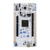
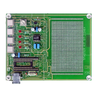
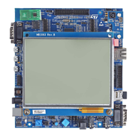
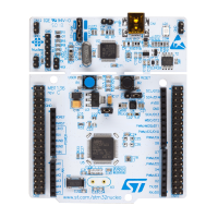
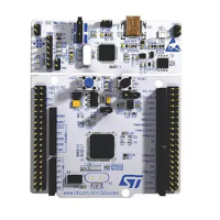
Two green LEDs (LD1 and LD2), located on the top middle side are available for the user. To light a LED a high
logic state HIGH must be written in the corresponding GPIO. Table 2 gives the assignment of the control ports to
the LED indicators.
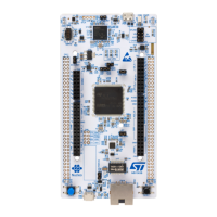
Two LEDs located on the top side, the red LD2 and the green LD1 (Refer to Figure 2), are available for the user.
To light a LED, a low-logic state HIGH must be written in the corresponding GPIO register. Table 4 shows the
assignment of the control ports to the LED indicators.
Table 4. Button and LED control port
Reference Color Name Comment
B1 Black Reset -
B2 Blue Wake-up Wake-up alternate function
LD1 Green LED1 PA5 (Alternate with ARD.D13)
LD2 Green LED2 PB14
LD3 Yellow
LED3 (Wi‑Fi
®
) PC9, Wi‑Fi
®
activity
LD4 Blue LED4 (BLE)
PC9, Bluetooth
®
activity
LD5 Green 5V Power 5 V available
LD6 Bicolor (Red and green) ST-LINK COM Green during communication
LD7 Red Fault Power Current higher than 750 mA
LD8 Red
V
BUS
OCRCR
PE3
LD9 Green
V
BUS
OK
5 V USB available
6.13
I
2
C addresses of modules used on MB1297
Table 5 displays the I
2
C read and write addresses for the modules that are connected to the I2C2 bus.
Table 5. I
2
C addresses for each module
Modules Description SAD[6:0] + R/W I2C write address I2C read address
HTS221
Capacitive digital sensor for relative
humidity and temperature
1011111x 0xBE 0xBF
LIS3MDL 3-axis magnetometer 0011110x 0x3C 0x3D
LPS22HB MEMS nano pressure sensor 1011101x 0xBA 0xBB
LSM6DSL
3D accelerometer and
3D gyroscope
1101010x 0xD4 0xD5
VL53L0X
Time-of-Flight ranging and gesture
detection sensor
0101001x 0x52 0x53
ST25DV04K Dynamic NFC/RFID Tag IC 1010x11x
0xAE for system
area
0xA6 for user
memory
0xAF for system
area
0xA7 for user
memory
STSAFE-A110 Highly secure solution 0100000x 0x40 0x41
UM2708
I2C addresses of modules used on MB1297
UM2708 - Rev 1
page 25/43
 Loading...
