6.3 Programming and debugging when the power supply is not from ST-LINK
(5V_ST_LINK)
It is mandatory to power the board first using CN2 (VIN) or CN9 (USB_FS_OTG), then to connect the USB cable
to the PC. Proceeding this way ensures that the enumeration succeeds, thanks to the external power source. The
following power sequence procedure must be respected:
1. Connect the jumper JP4 on (5V_ARD) or (5V_USB_FS).
2. Connect the external power source to CN2 in case of an ARDUINO
®
shield or to CN9 in case of USB FS
host interface.
3. Check that the red LED LD5 is turned ON.
4. Connect the PC to the USB connector CN7.
If this sequence is not respected, the board may be powered by V
BUS
first from ST-LINK, and the following risks
may be encountered:
1. If more than 500 mA current is needed by the board, the PC may be damaged or the current can be limited
by the PC. As a consequence, the board is not powered correctly.
2. 500 mA is requested at the enumeration, so there is a risk that the request is rejected and enumeration does
not succeed if the PC cannot provide such current.
6.4 Clock source
Three clock sources are described below:
• X1 8 MHz oscillator for the STM32L4S5VI microcontroller. This clock is not implemented in a basic
configuration.
• X2 32.768 kHz crystal for the STM32L4S5VI embedded RTC
• X3 8 MHz clock from the ST-LINK MCU for the STM32L4S5VIT6Umicroncontroller.
6.5
Reset sources
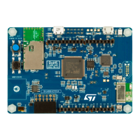
The reset signal of the B-L4S5I-IOT01A Discovery kit for the IoT node is active LOW and the reset sources
include:
• A reset button B1
• An ARDUINO
®
Uno V3 shield board from CN2
• An embedded ST-LINK/V2-1
6.6 USB OTG FS
The B-L4S5I-IOT01A Discovery kit for the IoT node supports USB OTG full-speed communications via the CN9
USB Micro-AB connector.
To do this, the following components must be added by the user:
• 8 MHz crystal (at X1 position). Reference is NX3225GD-8.00M
• 8.2 pF capacitor (0402 size) at the C2 position
• 8.2 pF capacitor (0402 size) at the C4 position
• 0-ohm resistor (0402 size) at the R5 position
• 0-ohm resistor (0402 size) at the R7 position
The B-L4S5I-IOT01A Discovery kit for the IoT node can be powered by the USB connectors at 5 V DC with
500 mA current limitation. A USB power switch (IC19) is also connected to V
BUS
and provides power to CN9. The
green LED LD9 is lit when either:
• The power switch is ON and the B-L4S5I-IOT01A Discovery kit for the IoT node works as a USB host,
• Or V
BUS
is powered by another USB host when the B-L4S5I-IOT01A Discovery kit for the IoT node works as
a USB device,
The red LED LD8 is lit when an over-current occurs.
UM2708
Programming and debugging when the power supply is not from ST-LINK (5V_ST_LINK)
UM2708 - Rev 1
page 16/43
 Loading...
