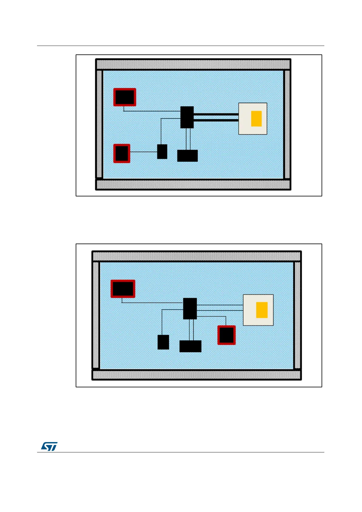
Figure 7: Sensor with a bad wiring on the PCB
In Figure 7: "Sensor with a bad wiring on the PCB "a wrong metal lines size is adopted, the
bigger dimensions will provide higher level of heating conduction. In Figure 8: "Sensor
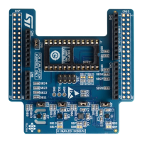
wiring with wrong placement on the PCB", the wrong placement of the sensor, close to a
device generating too much heating deteriorates the sensor performance.
Figure 8: Sensor wiring with wrong placement on the PCB
In both cases of thermal mechanism propagation, the infrared based thermal analysis of
the whole system, running in different working condition, is the right approach for identifying
the appropriate sensor location.