Reference design: integration and housing on a
personal device
3 Reference design: integration and housing on a
personal device
The example below describes how the sensor placement is implemented by following the
basic rules described in this document above; in other words by mounting the sensor as far
as possible from the main heating sources present on the board like display LDO and
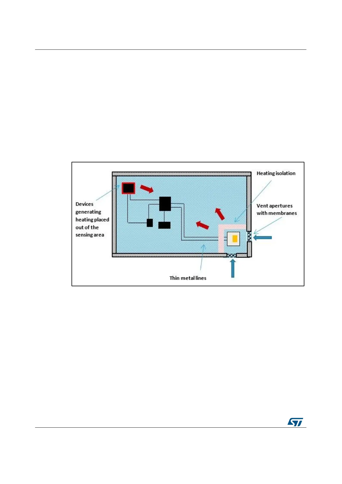
microcontroller that represent the more critical sources of heating. In Figure 16: "Integration
of the digital pressure sensor device in a sensor chamber with two vent apertures" is
shown the integration of the sensor in a sensor chamber isolated from the heating and with
two vent apertures covered with filter membranes. This solution provides at the same time
an efficient response time and a good protection from dust and light. In case of waterproof
device, a sensor chamber with one vent aperture is preferred.
Figure 16: Integration of the digital pressure sensor device in a sensor chamber with two vent
apertures
Based on the above recommendation, Figure 17: "Device integration reference in a
portable device" describes the integration in a portable device of the digital pressure sensor
in the bottom left corner. In this solution, a single vent aperture has been adopted (diameter
in the range of 0.5 mm) placing the sensor in the left corner, to simplify the integration with
the mechanical case and to maintain the right distance from other heating sources. A filter
membrane is also inserted for dust and water protection, depending on the specific
application.