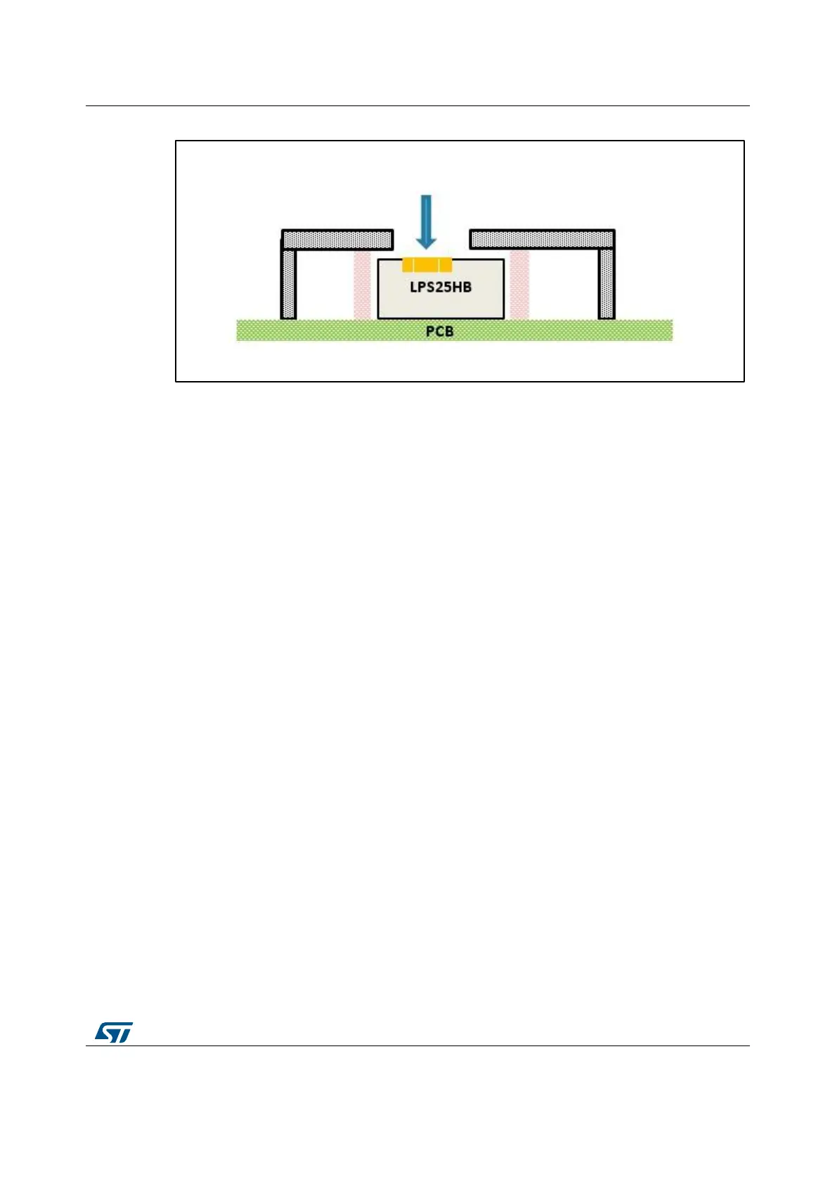
Figure 12: Good configuration for avoiding mechanical stress and reducing the dead volume
(b)
The figures above show correct and incorrect integration cases where, with the goal to
reduce the dead volume around the sensor to improve the pressure response time, the
embodiment structure is directly in contact with the sensor package, creating a mechanical
stress that can deteriorate the sensor performance. A minimal clearance has to be
maintained as in Figure 11: "Good configuration for avoiding mechanical stress and
reducing the dead volume (a)" and Figure 12: "Good configuration for avoiding mechanical
stress and reducing the dead volume (b)" to avoid any force applied on the sensor and
minimize the dead volume as well.
2.2 Sensor embodiment and housing
The sensor embodiment in the system shall match as much as possible the
recommendations highlighted above for the sensor placement and, on top of that, has to
provide all the features of specific application like waterproof, water resistant or resistant to
harsh environment, in case it is required.
Furthermore, the customer device design shall guarantee the air circulation from the
environment till the sensing area, first from the environment (outside) to the customer
device (inside), then internally from the aperture to the sensor housing and sensing
element as well. More efficient is the air circulation in this path, better the performances will
be.
The air path shall be well identified and sized in order to maximize the airflow, and as a
result, the final performance of the integrated system.
The pictures below represent a summary of a good case versus a bad case of sensor
embodiment and housing. In Figure 13: "Example of good sensor embodiment and
housing" a good design is described including also an optional filter membrane and PCB
cut to increase the thermal decoupling, that is a solution for specific case where the
devices around the pressure sensor are generating too much heating.