Hardware layout and configuration UM2206
16/55 UM2206 Rev 3
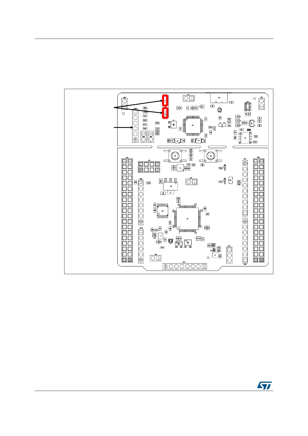
9.4.3 Using the ST-LINK/V2-1 to program/debug the STM32
To program the STM32, place the two jumpers marked in red on the connector CN2, as
shown in
Figure 8. Do not use the SWD connector to not disturb the communication with the
STM32 microcontroller of the Nucleo-64-P board.
Figure 8. ST-LINK debugger: jumper configuration for on-board MCU
9.4.4 Using the ST-LINK/V2-1 to program/debug an external STM32
application.
It is very easy to use the ST-LINK/V2-1 to program the STM32 on an external application.
Simply remove the two jumpers from CN2, as shown in Figure 9, and connect the
application to the SWD debug connector according to Table 6.
Note: JP4 NRST (target STM32 RESET) must be opened when CN3 pin 5 is used in an external
application.
SWD connector: CN3
ST-LINK jumper ON:
CN2 [1-2] and [3-4]

 Loading...