Connectors UM2206
38/55 UM2206 Rev 3
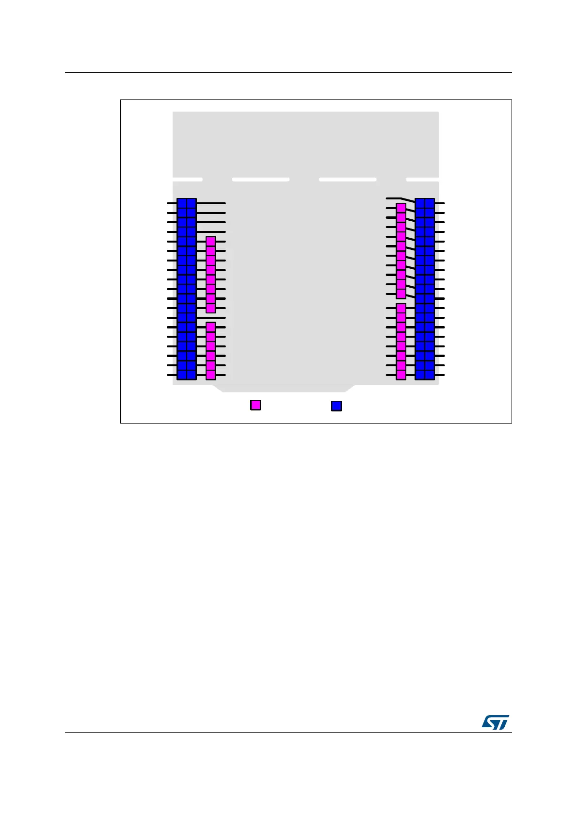
Figure 18. ST morpho connector pinout
Note: Arduino Uno V3 D0 and D1 signals are connected by default on USART1 (MCU I/O PA9
and PA10). Refer to
Section 9.9: Virtual COM port: LPUART1/USART1 for details about
UART interface modification.
10.4 External power connector
The external power connector CN11 is an 8-pin, single-row, 2.54 mm-pitch connector. By
default this connector is not soldered. The PCB footprint gives the possibility to easily
control the V
core
logic and the V
DD_MCU
power supply with an external source. The external
power connector is showed in
Figure 19.
PC0
PC1
PC2
PC3
PA1
PA0
NC
VIN
GND
GND
5V
3V3
NRST
IOREF
NC
GND
E5V
PD2
PC11
PB9
PB4
VBAT
PH1
PH0
PC15
PC14
PC13
NC
GND
PA14
PA13
PB12
NC
NC
BOOT0
VDD
PC12
NUCLEO_L4xxRx-P
PA2
PA3
PC4
AGND
PA4
PA5
PA6
PA7
PB1
GND
PB2
PB11
PA9
PA10
PB0
5V-STLINK
PC5
PC6
PC8
PB6
PA8
PA11
PB15
PB14
PB13
GND
AVDD
PB7
PB8
PC9
PA3/PA10
PA2/PA9
PA12
PB3
PB5
PA15
PB10
PC7
D8
D9
D10
D11
D12
D13
GND
AVDD
D14
D15
D0
D1
D2
D3
D4
D5
D6
D7
A5
A4
A3
A2
A1
A0
VIN
GND
GND
5V
3V3
NRST
IOREF
NC
Arduino
67Porpho
PC10
10
9
8
7
6
5
4
3
2
1
8
7
6
5
4
3
2
1
1
3
5
7
9
11
13
15
17
19
21
23
25
27
29
31
33
35
37
2
4
6
8
10
12
14
16
18
20
22
24
26
28
30
32
34
36
38
1
2
3
4
5
6
1
2
3
4
5
6
7
8
1
3
5
7
9
11
13
15
17
19
21
23
25
27
29
31
33
35
37
2
4
6
8
10
12
14
16
18
20
22
24
26
28
30
32
34
36
38
CN5 CN6CN7
CN9
CN8
CN10

 Loading...